

Modern industrial power systems and commercial HVAC networks need careful control of high-frequency noise. They also need solid chassis insulation. These steps matter for safety and steady performance. Electrical engineers, commercial technicians, and industrial system operators benefit when they learn the right way to set up an AC ground capacitor. Correct layout supports circuit safety and keeps processing lines running well. A clear step-by-step method protects sensitive controls from early failure and meets all electrical rules.
An AC ground capacitor works as a key filter in AC power lines. It creates a low-impedance path to ground or the metal chassis. This path moves unwanted high-frequency noise away from the main lines. Without proper grounding, leftover spikes and noise can return to control loops. The result is uneven system behavior and small arcs inside panels.

These capacitors often go into heavy-duty variable frequency drives (VFDs). They appear in commercial uninterruptible power supplies (UPS) too. Large renewable energy inverters use them as well. Multi-phase commercial motors and cooling systems include them because inductive switching creates voltage feedback. A clear grounding of an AC capacitor method keeps nearby digital parts safe from strong electromagnetic interference (EMI).
Work with AC systems requires strict safety steps. Technicians need insulated tools rated for the voltage. They also need safety goggles and a digital multimeter. A heavy-duty bleeder resistor tool must be ready before any AC capacitor wiring starts. This tool removes leftover charge from the dielectric and prevents shock.
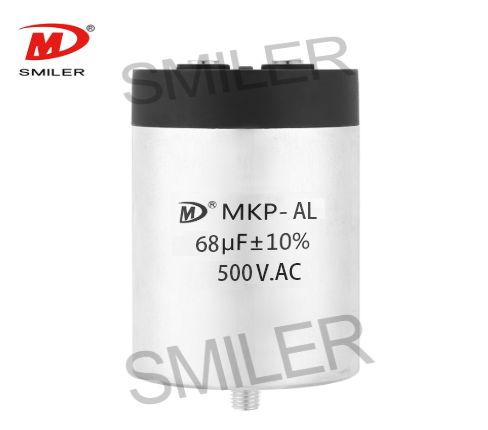
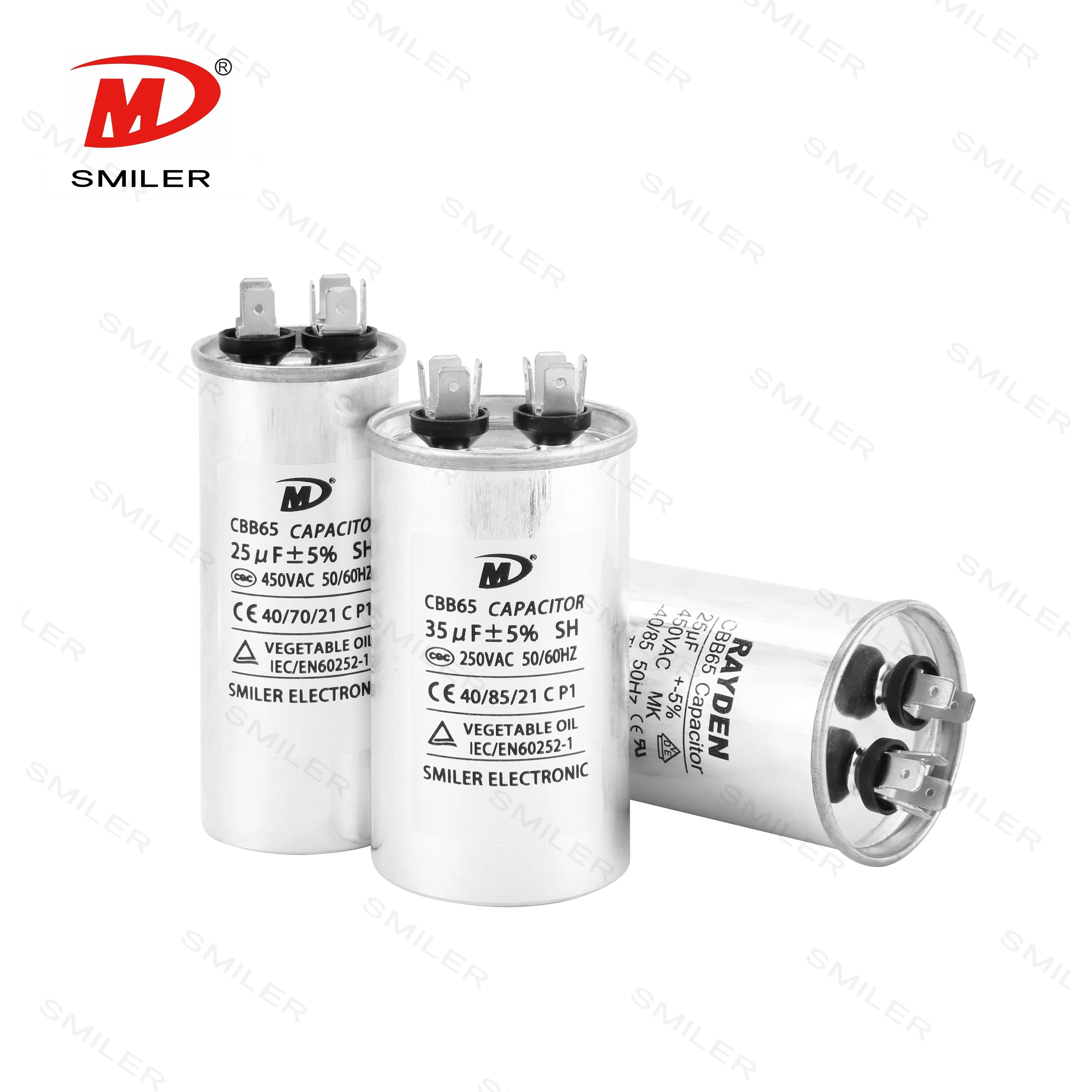
Reliable circuits depend on strong industrial parts with built-in safety. The CBB65 series from SMILER capacitor fits commercial cooling and motor systems well. It has a tough aluminum case and an explosion-proof design. The heavy-duty MKP-AL series works for advanced industrial needs that require strong harmonic control. It adds a secondary protection layer and a built-in overpressure cut-off. Over 15 years of film capacitor experience and a qualification rate above 99.93% support steady performance under heavy commercial loads.
Start by turning off the main circuit breaker. Check the system by eye. Use a digital multimeter to confirm zero voltage at the terminals. Connect the insulated discharge tool across the terminals. This step removes any remaining charge before you touch the connections.
Look at the terminal labels on the unit case. Dual-run models like the CBB65 Capacitor show markings such as C (Common), FAN, and HERM. For industrial setups, locate the grounding stud or chassis point. This helps you follow the correct AC capacitor wiring diagram path.

Vibration can loosen wires and harm internal parts over time. Bolt the mounting bracket or metal case firmly to the frame inside the cabinet. Use the correct torque values. This creates a steady electrical bond between the case and the system ground.
Crimp good tinned-copper lugs on the lead wires. This lowers connection resistance. Attach the active leads to the matching load terminals per the layout drawings. Connect the main ground wire from the busbar to the dedicated ground post. Use spring washers so the AC-Filter capacitor wiring connections stay tight and resist heat loosening.
Check every connection by hand. Make sure terminal screws are tight, and no stray wires touch insulation gaps. Close the panel door. Restore main power and measure current balance to confirm correct phase operation.
Wrong terminal connections or reversed wiring can cause a line-to-ground fault. This fault creates sudden overcurrent, melts the dielectric, produces heat, and triggers arc flashes inside the enclosure.
Poor AC capacitor wiring lets high-frequency currents travel freely along system rails. These currents can reach sensitive microcontrollers and modules. The result is signal errors, false faults, and early failure of costly parts.
Add hardware checks to regular plant maintenance. Look at the outer case for bulging, cracks, or leaks. Measure microfarad values with a digital meter. Confirm readings stay inside the stated ±5% or ±10% tolerance.
Watch for loud motor hum, ongoing voltage faults on inverter screens, or an active safety cut-off light. Premium MKP-AL or CBB65 units from SMILER capacitor include safe shutdown features. Replace worn units quickly to avoid unplanned shutdowns.
A: Non-polarized film types let either terminal connect to the AC phase. Dual-run units like the SMILER capacitor CBB65 still require correct C, FAN, and HERM connections for separate motor circuits.
A: A broken ground wire stops high-frequency harmonics from reaching earth. Noise then spreads to nearby boards and variable frequency drives. The metal chassis can also reach higher voltages and create shock hazards for operators.
A: Look for a warped top, swelling, or oily residue at the terminals. A multimeter reading that falls outside the ±5% or ±10% range shows the unit needs replacement.
A: No. High-performance film capacitors can hold dangerous charge long after power is removed. Always use a bleeder resistor or insulated discharge tool across the terminals before touching any part of the AC capacitor wiring diagram path.
A: No. Industrial filter types such as the SMILER capacitor MKP-AL series handle continuous high-frequency harmonics in parallel setups. Standard single-phase motors need run-rated units like the CBB60 or CBB65 series. These provide the right phase shift and safety class for rotating equipment.
Exploring How AC Capacitors and DC Capacitors Function Differently
Mastering AC to DC Rectifier with Capacitor Techniques
Understanding Why Capacitors Pass AC but Block DC in Circuits
What Drives AC Capacitor Cost? A Comparison with DC Capacitors
CBB65 250VAC Capacitor Explained: What Every Professional Should Know


 Add
Building 12,Huazhi Technology Innovation Center,28 Sanle East Road,Beijiao,Foshan,Guangdong,China
Add
Building 12,Huazhi Technology Innovation Center,28 Sanle East Road,Beijiao,Foshan,Guangdong,China
 Phone
+86 18007576965 / 0757-22391591
Phone
+86 18007576965 / 0757-22391591
 Email
ari@sml-cap.cn
Email
ari@sml-cap.cn


