

In modern power electronics, the ability to manage high-speed switching transitions is paramount for efficiency and device longevity. An RCD snubber, composed of a resistor, a capacitor, and a diode, acts as a critical passive network designed to clamp voltage transients. Proper RCD snubber capacitor sizing is the foundation of this circuit. Its primary function is to absorb the energy stored in leakage inductance when a power switch turns off, preventing catastrophic voltage spikes that could exceed the breakdown voltage of semiconductors. Without this energy absorption, the semiconductor switch—whether a MOSFET or IGBT—is susceptible to repetitive stress, leading to premature failure.
The diode in the RCD setup charges the capacitor during the switch-off transient. This action limits voltage overshoot across the switch. The capacitor then releases its stored energy through the resistor. This release happens before the next switching cycle. A good balance in this charge-discharge process remains essential. Engineers select high-quality metallized film capacitors to support reliable energy transfer. These capacitors also provide low ESR (Equivalent Series Resistance). Low ESR helps maintain strong clamping performance in fast-switching conditions.

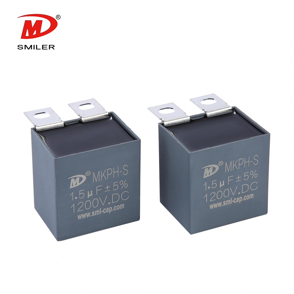
Electric vehicle chargers use these circuits. Industrial motor drives need them as well. Renewable energy inverters also depend on them. High-frequency power electronics count on solid protection networks. Converters continue to shrink in size. This shrinkage raises component density. As a result, the thermal and electrical behavior of the snubber network grows more important. When designers add these circuits, they often choose components such as SMILER capacitor MKPH-S film capacitors. These parts deliver the required stability and voltage handling. They perform especially well in tight spaces that call for compact high-performance solutions.
Accurate calculation decides the survival of the power switch. The capacitor must carry a rating that covers the peak voltage transient. It also needs an extra safety margin. This margin prevents dielectric breakdown. Designers must consider parasitic inductance from the PCB layout. This inductance greatly affects the energy the snubber must handle. High-reliability parts like the MKPH-S Series keep these ratings stable for a long period. Precise math separates a dependable design from one that fails in the field.
The choice of capacitance value requires careful balance. Capacitance that is too small weakens the clamping action. Voltage spikes can then reach the switch and cause damage. On the other hand, capacitance that is too large raises switching losses. It also puts extra load on the diode and resistor. Many engineers use digital simulation tools to locate the best value. At this value, ringing stays suppressed, and power dissipation remains low.
The snubber diode needs ultra-fast recovery. This feature lets it respond right away to transients. The resistor must manage pulse power dissipation in every cycle. Consistent quality matters when suppliers provide these parts. SMILER capacitor supplies custom solutions. Our MKPH-S capacitors work together with exact diode and resistor choices. This combination creates an improved thermal profile for high-frequency needs.
The best way to cut energy absorption in the snubber is to reduce parasitic inductance. Designers achieve this by keeping the loop area small between the switch and snubber parts. A smaller loop area lowers the height of voltage ringing. This change supports smaller and more efficient snubber networks. Overall, switching losses drop as a result.
Different switching devices need different snubber setups. High-speed MOSFETs often work best with lower capacitance values. They also require higher dV/dt ratings than slower IGBTs. Custom adjustments frequently become necessary for top performance. SMILER capacitor's technical method adjusts MKPH-S metallized film capacitors to match specific gate-drive traits and peak currents. These adjustments ensure good compatibility under various load conditions.
Physical layout holds equal importance to the circuit diagram. Engineers should position components close to the power switch. Close placement reduces lead inductance. Wide and short traces work best for the snubber loop. Correct trace routing stops the snubber from creating EMI (Electromagnetic Interference). This practice keeps the converter in line with industry rules.

Many designers start with standard component values. They forget to check these values against the real parasitic details of the prototype board. Oversized parts create large and inefficient circuits. Undersized parts cause reliability problems. A sensitivity study on capacitance versus expected switching frequency helps avoid these issues.
The snubber resistor can produce notable power dissipation. Engineers must consider ambient temperature and the thermal path of the resistor. Without this review, hot spots may form on the PCB. The chosen resistor should handle RMS power dissipation. It must do so without performance loss over time.
RCD snubbers can function well at normal loads. They sometimes fail at light loads or during sharp transients. Full testing is therefore necessary. This testing includes cold-start runs and full-load high-temperature checks. Such tests confirm that the snubber circuit design stays effective across the complete operating range of the converter.
Switching frequencies now reach the megahertz range. Older capacitor materials are giving way to new dielectrics. These new materials provide lower loss and better temperature stability. The changes allow high-frequency power electronics to run with less heat. Higher power density becomes possible as a result.
The year 2026 brings wider use of AI-assisted circuit simulation. These tools study parasitic layouts in three dimensions. They then suggest optimized values for RCD snubber capacitor sizing. Engineers receive these values before any prototype is built. SMILER capacitor applies these analysis methods during product development. The company often validates results with its MKPH-S series. This process confirms that the film capacitors satisfy the demands of future power systems.
Countries worldwide aim for carbon neutrality. Efficiency rules for power supplies grow stricter each year. Meeting global safety and performance standards for passive parts is now a basic requirement. Certified high-quality components have become necessary for any design that seeks worldwide market access.
A: In high-frequency power electronics, the rate of change of current (di/dt) produces large voltage transients. An incorrect capacitor size lets the clamping circuit miss these spikes. The semiconductor switch may then break down, and the converter can fail.
A: Repeated voltage spikes above the rated blocking voltage of a MOSFET or IGBT create localized stress. This stress hits the gate oxide and semiconductor junctions. The device may survive at first. Still, the transients speed up wear and shorten the working life of the power stage.
A: Important parameters include low Equivalent Series Resistance (ESR) and low Equivalent Series Inductance (ESL). These traits support fast energy absorption. High voltage endurance and stable dielectric behavior under frequency stress and heat are also required. The MKPH-S series shows these features.
A: Poor circuit design often uses excess capacitance. The snubber resistor must then dissipate extra energy. This raises the thermal load on the PCB. Nearby parts may exceed their temperature limits. System stability suffers as a result.
A: Mounting style affects parasitic inductance directly. Low-inductance terminals help. The shortest possible lead lengths to the power switch loop are also necessary. These steps keep high-frequency performance at the required level.
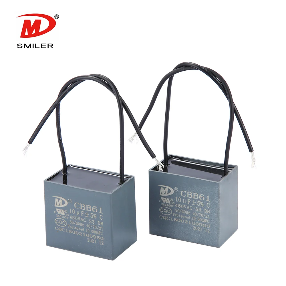
What Does a CBB61 Fan Capacitor Do? Exploring the Role of CBB61 Fan Capacitors
RCD Snubber Capacitor Selection: Measures for Surge Suppression
RCD Snubber Capacitor vs RC Snubber: Key Performance and Design Insights

Top RCD Snubber Capacitor Types for 2026 Inverters
Best RCD Snubber Capacitor in 2026: A Guide for IGBT and Power Supply Design


 Add
Building 12,Huazhi Technology Innovation Center,28 Sanle East Road,Beijiao,Foshan,Guangdong,China
Add
Building 12,Huazhi Technology Innovation Center,28 Sanle East Road,Beijiao,Foshan,Guangdong,China
 Phone
+86 18007576965 / 0757-22391591
Phone
+86 18007576965 / 0757-22391591
 Email
ari@sml-cap.cn
Email
ari@sml-cap.cn


