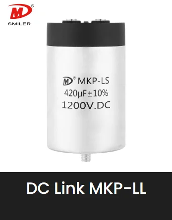
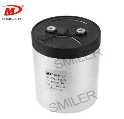
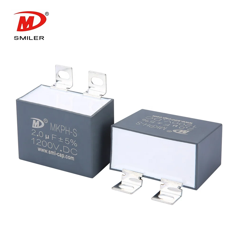
An open circuit in an AC filter capacitor can interrupt the intended filtering path, increase ripple or harmonic content, and expose connected equipment to operating conditions it was not designed to handle. The exact effect depends on where the capacitor sits, the converter topology, and whether the filter uses one component or a bank. Engineers need to distinguish a genuinely open capacitor from a failed connection, a blown fuse, or a measurement made under the wrong conditions.
An AC filter capacitor provides a frequency-dependent path in a designed network. In a converter output filter, it works with inductors and other components to attenuate unwanted frequency content while allowing the intended AC output to pass. The capacitor is not a universal noise absorber: its effect depends on its capacitance, equivalent series resistance, inductance, placement, and the impedance of the surrounding circuit.
When the capacitor becomes electrically open, that branch no longer provides its designed capacitive path. The resulting waveform may show higher ripple, more switching residue, altered resonance, or increased stress on nearby components. A system with parallel branches may continue to run, which can hide the failure while shifting more current into the remaining branches.
Symptoms are rarely unique to a capacitor. Increased distortion can come from a disconnected lead, cracked solder joint, open fuse, failed switching device, changed load, or a control problem. A low capacitance reading may indicate aging or repeated self-healing rather than a clean terminal break. Diagnosis should therefore follow the circuit path instead of replacing the first component that looks suspicious.
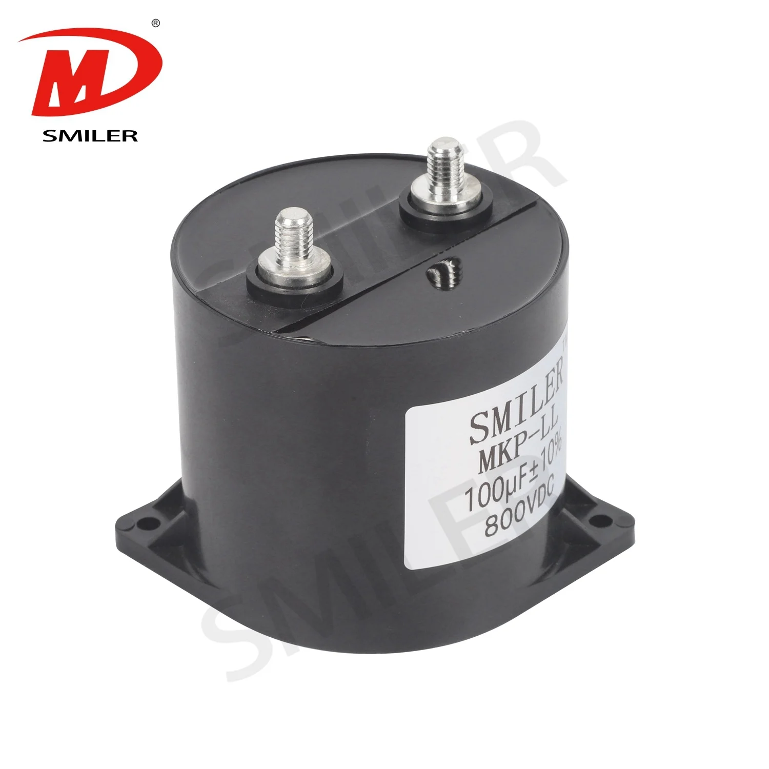
Film capacitors can fail open when an internal connection between metallization, end spray, and terminal is interrupted. Repeated electrical and thermal stress, vibration, or mechanical strain at the lead can contribute to a loss of continuity. Poor support or a lead bent sharply at the case may transfer stress into the termination. Inspection can reveal a loose terminal or damaged joint, but an intact exterior does not prove that the internal path is healthy.
Voltage transients and excessive ripple current can raise local electrical and thermal stress. Metallized film can clear a small dielectric defect through self-healing, but many events can reduce effective electrode area and capacitance over time. Self-healing is a design behavior, not immunity to sustained overvoltage, excess temperature, or operation beyond the component's ratings.
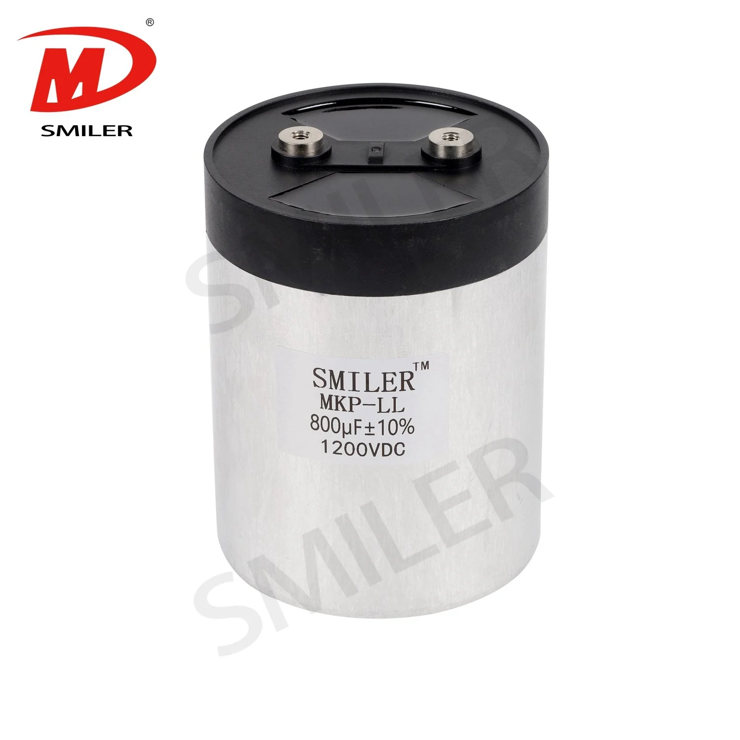
In an AC filter, the relevant checks include RMS ripple current, peak voltage, switching frequency, ambient and hotspot temperature, cooling, and the expected lifetime. The AC Filter Capacitor MKP-AM uses metallized polypropylene film, a plastic shell, and resin filling rated UL94 V-0. Its published application includes output AC filtering for power converters, UPS, and motor drives. Those component facts do not establish suitability for every design; selection still requires validation against actual electrical and thermal conditions.
The immediate risk may be degraded waveform quality rather than a complete shutdown. Sensitive loads can experience excess ripple or electromagnetic interference, while the converter may run hotter or trigger a protection response. In a parallel capacitor bank, remaining components can carry more ripple current and heat. In a resonant network, losing capacitance can shift the resonant point and change component voltage stress. The outcome depends on system protection, redundancy, and the location of the open branch.
Follow the equipment manufacturer's lockout and discharge procedure. Capacitors can retain hazardous energy after input power is removed, so verify the absence of voltage with appropriately rated equipment before touching terminals. Do not short a capacitor with a screwdriver or assume that a visible discharge resistor has worked.
After safe isolation, inspect the component body, terminals, lead joints, board pads, and nearby fuse or wiring. Look for cracking, swelling, discoloration, loose hardware, corrosion, or a lifted pad. Record the installed part markings and wiring before disconnection so that a replacement is not selected from appearance alone.
Check continuity through the external path, including fuses, connectors, busbars, and solder joints. If the reading is ambiguous in circuit, isolate one terminal according to service procedures. A capacitance meter or LCR meter can assess the component out of circuit; compare the result with the marked value and tolerance. A measurement near nominal does not verify performance at rated voltage, ripple current, or operating temperature.
For an energized system, waveform and current measurements should be made only by a qualified technician using instruments, probes, clearances, and procedures suitable for the circuit's voltage category. Comparing operating waveforms with a known-good baseline can help locate the affected filter stage, but it does not replace de-energized component checks.
Before replacing a part, identify why it failed. Verify voltage and ripple margins, thermal environment, mounting, connection quality, and the capacitor's intended AC filtering duty. The MKP-AM AC filter capacitor product page describes the product family. This page supports product identification, not a design approval for a particular converter.
The AC Filter Capacitor MKP-AM uses metallized polypropylene film, a plastic shell package, and resin filling rated UL94 V-0. Published features include large capacitance, small size, excellent over voltage and over current capability, high reliability, self-healing property, and long lifetime. Its published applications include output AC filtering for power converters, UPS, and motor drives. These facts describe a product family and do not replace validation of a real converter design.
The product family is intended for output AC filtering in power converters, UPS equipment, and motor drives. Its construction and feature set are component-level facts: metallized polypropylene film, a plastic shell package, resin filling rated UL94 V-0, large capacitance, small size, over-voltage and over-current capability, high reliability, self-healing property, and long lifetime. Final selection still requires voltage, RMS ripple current, thermal, mounting, frequency-response, insulation, and lifetime verification under the real operating conditions.
Base selection on the maximum continuous and transient voltage, RMS ripple current spectrum, frequency, ambient temperature, cooling, and expected service life. Account for tolerances and worst-case operating conditions. In banks, verify current sharing and consider how a single open branch affects the remaining capacitors. Do not substitute a higher capacitance or a different package without checking resonance, inrush, protection, and mechanical constraints.
Provide mechanical support so vibration and transport loads do not act directly on capacitor leads. Use suitable bend radii and strain relief, and confirm that soldering or bolted connections meet the component's installation requirements. Production checks can include visual inspection, electrical testing, and waveform monitoring relevant to the system. Trend data helps distinguish a component issue from an upstream operating change.
SMILER capacitor supplies film capacitor families for power electronics applications. Our engineering discussions can use the actual bus voltage, ripple-current profile, switching frequency, temperature, mounting, and lifetime target to identify the information needed for a component review. A product family should be treated as a candidate for evaluation, not an automatic drop-in replacement. Review the AC filter capacitor category for broader product context.
A: It means the capacitor branch no longer provides electrical continuity through its intended internal and terminal path. The effect on filtering depends on the circuit topology and the location of the failed branch.
A: Yes. A terminal or internal connection can open while the case looks normal. Electrical measurements and inspection of connected joints are needed to distinguish an internal failure from an external open.
A: Possible effects include increased ripple or harmonic content, changed resonance, protection trips, excess stress on parallel components, or degraded output quality. These symptoms can also have other causes.
A: No. A capacitance measurement does not establish performance under rated voltage, ripple current, frequency, temperature, or operating time. Check the component and circuit under appropriate service procedures.
A: Engineers can validate voltage and ripple margins, control hotspot temperature, support terminals against vibration, verify connection quality, and review bank behavior if one branch opens. The checks should reflect the real operating profile. For motor-driven filter assemblies, the CBB61 capacitor family offers a separate reference point for comparing film construction and application boundaries.
 Add
Building 12,Huazhi Technology Innovation Center,28 Sanle East Road,Beijiao,Foshan,Guangdong,China
 Phone
+86 18007576965 / 0757-22391591
 Email
ari@sml-cap.cn