An EV traction inverter converts battery power into the controlled three-phase current that drives the motor. Between the battery and the switching bridge, the DC link must stay electrically stable while current changes rapidly during acceleration, regeneration, and torque transitions. That makes the DC-Link Capacitor more than a bulk energy reservoir: it is a high-frequency current path, a voltage-ripple control element, and a thermal design constraint.
For engineers selecting a film capacitor, the practical question is whether it can absorb ripple current, switching pulses, voltage stress, heat, and mechanical constraints over the vehicle's duty cycle.
A traction inverter draws pulsed current from the DC bus. The battery and busbar carry lower-frequency flow; the DC-Link Capacitor supplies local high-frequency current to the switching bridge. Current stress depends on modulation, switching frequency, motor operating point, phase-current waveform, bus impedance, and distance to the power modules.
A capacitor selected only by nominal capacitance can therefore underperform. Similar microfarad values may see different RMS ripple, peak current, voltage overshoot, and self-heating in different layouts. Start with the inverter's worst-case operating points, not a catalog value alone.
Ripple current produces loss through equivalent series resistance and dielectric losses. The loss becomes heat, changing the margin available for the film, metallization, terminals, potting, and enclosure. Temperature cycling can also stress connections.
Review RMS ripple at the relevant frequencies, peak transient current, hot-spot temperature, cooling, and voltage derating. Record each value with its DC bus voltage, switching frequency, ambient temperature, cooling method, and test duration. Without that context, a single ripple-current number is hard to compare.
The DC-Link Capacitor lowers the impedance seen by the inverter bridge. It also limits high-frequency bus-voltage ripple and supplies local energy during short current changes. Capacitance, ESR, ESL, layout, and current sharing all need to be considered together.
Film construction is attractive because metallized polypropylene can combine low loss, self-healing behavior, and pulse capability. The assembly matters. Busbar inductance, terminal geometry, current-loop area, cooling, and clamping can rival the capacitor body.
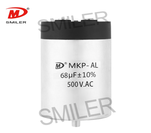
Local application material describes a dry-type DC-Link Capacitor as a metallized polypropylene film component with an aluminum shell and resin filling. It links that construction with low ESR, low inductance, self-healing behavior, long life, and high ripple-current handling. The same material lists DC-Link use in EV or HEV transportation, wind and solar inverters, motor-driver systems, welders, elevators, and UPS equipment.
The physical loop from capacitor terminal to switching module should be short and low inductance. A longer path adds inductance and can turn a switching edge into voltage overshoot. Evaluate the capacitor bank with the busbar and power module, not in isolation.
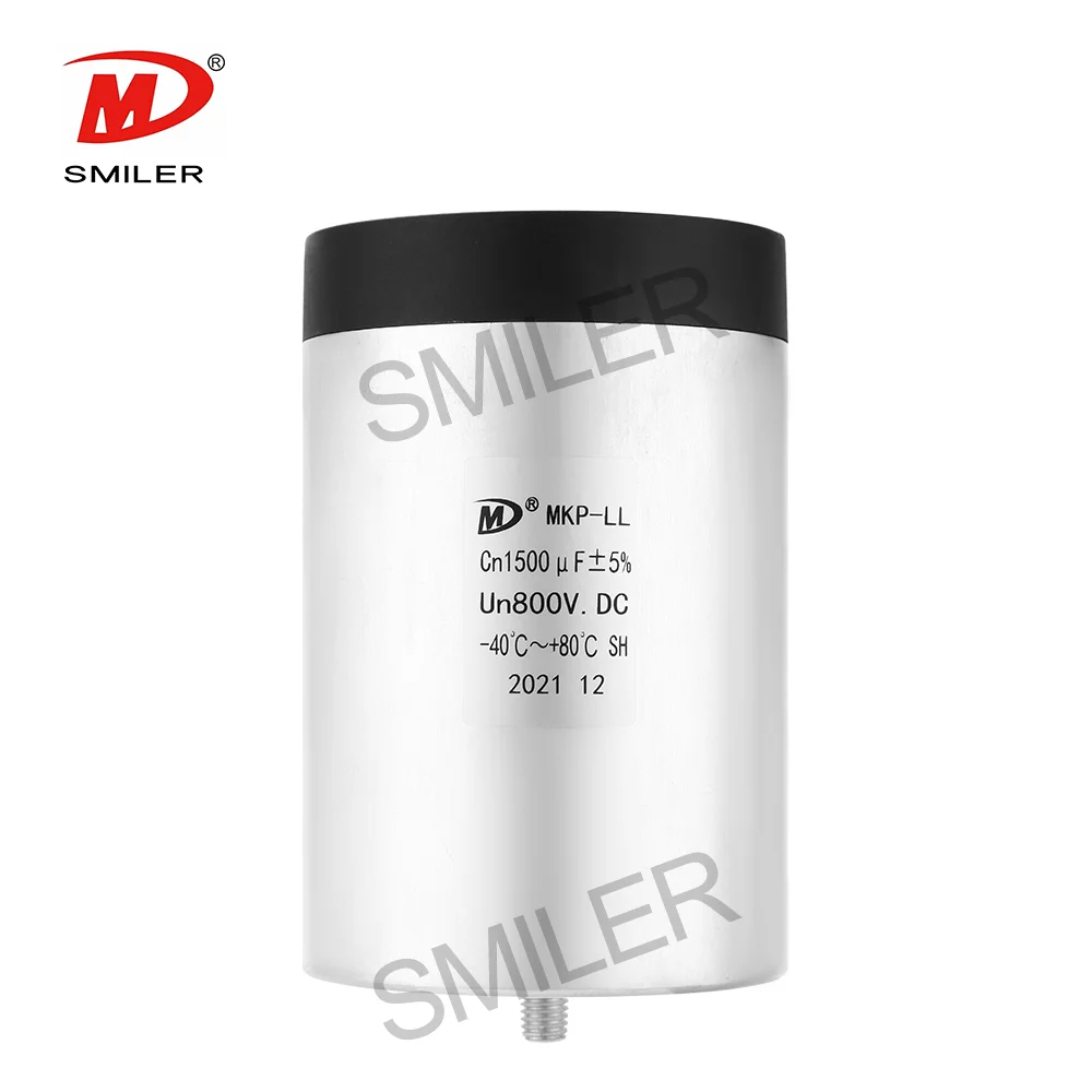
The Power Capacitor DC Link Capacitor MKP-LL is listed for DC-Link circuits, renewable energy, industrial drives, and traction applications. The official product page specifies 600-4000 VDC and 24-5600 uF, with low ESR and high ripple-current handling capabilities. Those ranges are a starting point for matching the DC bus and energy requirement; they are not a substitute for application-specific ripple and thermal verification.
RMS ripple current is a thermal limit, while peak current is a transient and connection-stress concern. Both should be checked. Low ESR helps reduce resistive loss, but the capacitor's ESL and the surrounding busbar determine how effectively it handles fast switching edges. A good review therefore includes an electrical model or measurement of the capacitor, busbar, power module, and current sensors as one loop.
Mechanical details also matter. Terminal spacing, current direction, mounting pressure, insulation distance, potting, and cooling contact affect temperature rise. In parallel banks, symmetrical connections help divide current; unequal path resistance or inductance can force one unit to carry more ripple.
The specification material also describes plastic-case DC-filter capacitors with low self-inductance and equivalent series resistance, strong tolerance of impacting current, and use in AC/DC filtering, inverter welders, UPS equipment, and electric vehicles. In practice, that supports a system-level reading of high-ripple capability: frequency, transient profile, and installation conditions must be named.
Rated DC voltage must exceed the maximum bus voltage. This covers regenerative rise, control tolerance, and switching overshoot. Temperature should be measured at the capacitor hot spot, not only at the enclosure inlet. The specification material describes a dry-type DC-filter range from -40 C to +85 C, with temperature derating above the reference condition. Treat those values as a product-specific example, not a universal limit. Film capacitors can provide self-healing after a localized dielectric fault. However, self-healing does not remove the need to control repeated overvoltage, excessive current, or sustained heat.
For an HEV/EV onboard charger, the application sheet describes DC-link capacitors as components for DC filtering and smoothing. It lists 1-170 uF, 450-1200 VDC, and automotive-grade AEC-Q200. Those figures describe that OBC application sheet, not a universal traction-inverter requirement. They show why the DC bus, qualification, and duty cycle must be specified together.
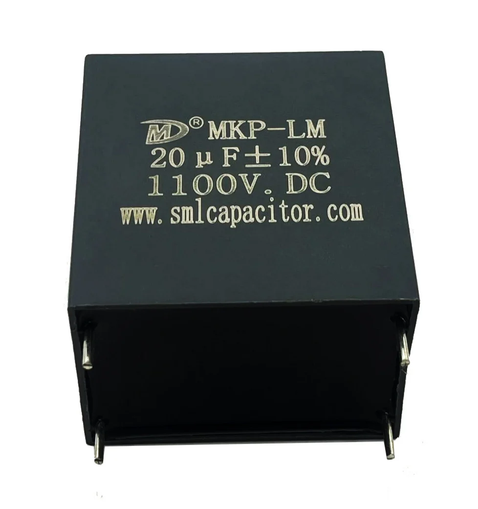
The MKP-LM (THB-Type) DC-Link capacitor is a compact plastic-case option listed for 500-1200 VDC and 1-110 uF, with a hot-spot temperature up to 105 C. Its high-humidity resistance and automobile DC-DC application information may be useful when the vehicle platform needs a smaller DC-link stage or a harsh-environment design. Confirm the actual traction-inverter duty cycle before treating it as a drop-in replacement for a larger aluminum-case bank.
Start with the electrical envelope: minimum and maximum DC bus voltage, required energy, allowed ripple voltage, ripple-current spectrum, and fault or regeneration conditions. Then compare capacitance tolerance, terminal arrangement, dimensions, mass, cooling surface, and service clearances. A physically smaller part can simplify packaging, but it may need parallel units or a different terminal arrangement to meet the same current requirement.
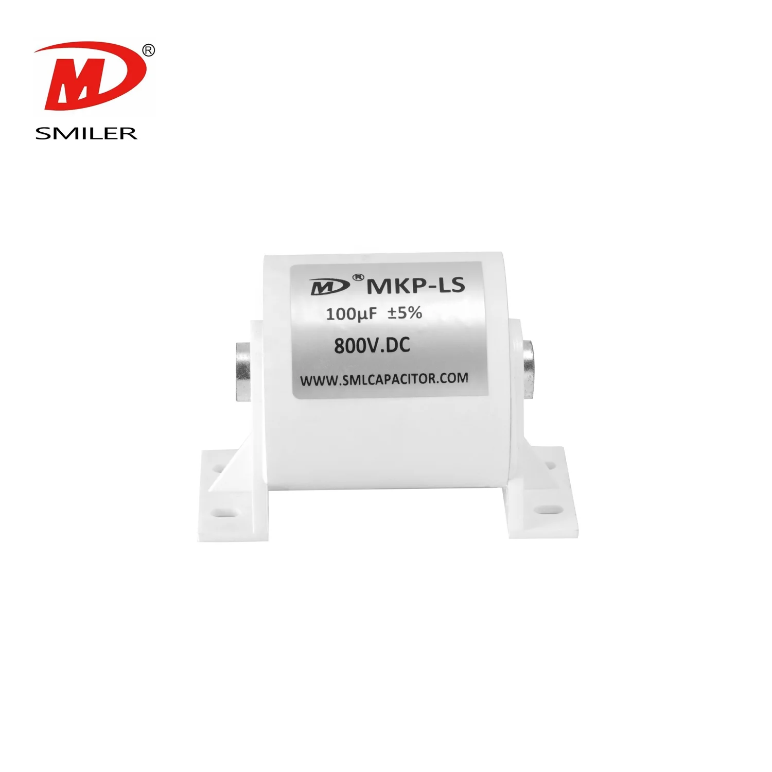
The DC-Link Capacitor product range includes multiple constructions rather than one universal part. This matters because an EV traction inverter may prioritize high current and low inductance, while an auxiliary converter may prioritize compact dimensions, humidity performance, or easier PCB and busbar integration.
An aluminum-case construction can suit a high-energy DC bus and a mechanically supported module. A plastic-case construction can suit a more compact converter where insulation, humidity, and mounting details are central. A Mylar-tape or small terminal style can be useful in high-frequency or high-current assemblies when the current loop and heat path are controlled.
SMILER capacitor supplies film capacitors for DC-link, filtering, and other power-electronics applications. We can review the DC-bus voltage, ripple-current profile, and installation space before recommending a product family. That review is most useful when the customer provides the inverter waveform, busbar drawing, temperature limits, expected service life, and any automotive qualification requirement.
Before design release, verify the capacitor at the electrical and mechanical levels. Confirm the DC voltage margin, capacitance at temperature, RMS ripple current, peak current, hot-spot temperature, insulation distances, terminal torque, and cooling path. Check whether the test waveform represents acceleration, steady cruising, regenerative braking, and fault recovery rather than only a laboratory sine wave.
Review the complete current loop. Measure bus voltage at the switching module, and check ringing, uneven current sharing, and local hot spots around terminals or busbar joints.
This would include assembly tolerances, clamping, potting/resin condition, routing of the connectors, vibrations, humidity, and thermal cycles. Serviceability issues would also involve how the capacitor can be examined, replaced, discharged, and isolated.
A: It stabilizes the DC bus, supplies local high-frequency current to the switching bridge, and helps limit voltage ripple when the motor current changes quickly.
A: High ripple current increases internal loss and temperature. The capacitor must handle the expected RMS current and peak transients without exceeding its electrical, thermal, or service-life limits.
B: No. Increased capacitance helps in reducing the voltage ripple but at the same time increases the inrush current and mass/volume and other factors. It all depends upon the complete DC bus structure.
A: RMS and peak currents, switching frequency, ESR and ESL, hotspot temperatures, inductance of the busbar, voltage spikes, cooling, and current sharing at full car duty cycles.
A: No. Aluminum-case, plastic-case, and other constructions may suit different voltage, energy, humidity, thermal, terminal, and packaging requirements. Selection should follow measured system conditions.
 Add
Building 12,Huazhi Technology Innovation Center,28 Sanle East Road,Beijiao,Foshan,Guangdong,China
 Phone
+86 18007576965 / 0757-22391591
 Email
ari@sml-cap.cn