

A capacitor does not just allow all AC signals to pass. It does not stop all DC voltages either. Its opposition to current flow varies steadily with frequency. The result therefore depends on the capacitance. It also depends on circuit resistance. Component placement plays a key role. The exact point where the output is measured affects the outcome.
The opposition created by an ideal capacitor is called capacitive reactance. It is expressed as Xc = 1/(2πfC), where f is frequency and C is capacitance. Because frequency appears in the denominator, lowering the frequency raises the reactance. A 1 µF capacitor presents far more reactance at 10 Hz than at 10 kHz.
The same behavior can be viewed through i = C(dv/dt). A slowly changing voltage produces less capacitor current, while a rapidly changing voltage produces more. Low-frequency AC therefore encounters a comparatively difficult path through a series capacitor.
A series RC circuit uses the capacitor and resistor to create a voltage divider. This divider changes with frequency. At low frequency, most of the input voltage drops across the capacitor. Its reactance is high at this point. The circuit current stays small. The voltage across the output resistor or load therefore remains small as well.
When frequency increases, the capacitive reactance decreases. More current than flows to the load. The output voltage increases in turn. This process shows why capacitors serve as filters in AC circuits. They block low-frequency signals effectively. This occurs when the capacitor is placed in series with the signal path. The output is taken across the resistance.
At very low frequency, a series capacitor approaches open-circuit behavior. It charges and discharges slowly, and its voltage follows much of the applied signal. Little current is available to create an output across the load. At zero frequency, an ideal capacitor passes no steady-state current after charging.
A practical high-pass stage does not completely reject every signal below its cutoff. Attenuation becomes greater as frequency moves farther below the cutoff. A first-order RC response changes at approximately 20 dB per decade.
Higher-frequency voltage reversals repeatedly charge and discharge the capacitor. Its reactance becomes small compared with the load resistance, so a larger share of the input appears across the load. Engineers use this relationship for coupling between amplifier stages, removing slow sensor drift, and suppressing low-frequency rumble.
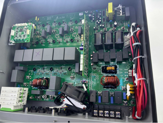
The principle is also useful when evaluating different AC-filter capacitor options, but a product's filter function must be interpreted together with its circuit position. A shunt AC filter capacitor may remove high-frequency harmonics instead of blocking the low-frequency fundamental.
For an ideal first-order high-pass RC filter, the cutoff frequency is fc = 1/(2πRC). At this point, capacitive reactance equals resistance, and output magnitude is about 70.7% of the passband value, or -3 dB. The cutoff is a reference point, not a wall.
A larger capacitance lowers the cutoff because it offers less reactance at a given frequency. A larger resistance also lowers the cutoff because the capacitor's reactance becomes small relative to that resistance sooner. Both values should be selected from the required lowest pass frequency.
The resistance in the formula must represent the resistance actually seen by the capacitor. It may include source resistance, a bias network, the input resistance of the following stage, and the load. If the load changes, effective resistance and cutoff frequency can change as well.
A coupling capacitor that meets the target cutoff with a high-impedance input may attenuate too much low-frequency content with a lower-impedance load. Good design calculates the worst-case effective resistance and checks the response across component tolerances.
The series capacitor creates the high-reactance barrier that attenuates low-frequency current. With the load connected after the capacitor and the output measured across that load, low frequencies are reduced while higher frequencies pass. The output node must always be identified.
A capacitor is a frequency-dependent impedance, not a complete filter by itself. The surrounding resistance and chosen output determine whether the circuit behaves as a high-pass or low-pass network.
When a capacitor is connected from the output node to ground, its falling high-frequency reactance gives unwanted high-frequency current an easier path away from the load. Low frequencies remain at the output because the capacitor has high reactance there. This arrangement is a low-pass filter.
Power-converter output filters often use this shunt behavior to reduce switching harmonics while preserving the lower-frequency AC waveform. The phrase "capacitor blocks low frequency" is therefore accurate only for a suitable series high-pass topology.
Real capacitance can differ from its nominal value, moving the cutoff frequency. Equivalent series resistance adds loss, while equivalent series inductance becomes important as frequency rises. At self-resonance, inductive behavior begins to dominate, so the basic reactance equation no longer predicts the full response.
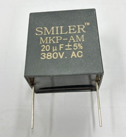
For power-converter output filtering, the Power Capacitor AC Filter Capacitor MKP-AM uses metallized polypropylene film and is intended for output AC filtering in power converters, UPS systems, and motor drives. That application commonly targets high-frequency harmonics, showing why topology matters as much as the capacitor label.
Circuit-board traces, wiring, source impedance, and the input capacitance of the next stage modify the measured response. A single calculated cutoff may become several interacting poles and zeros. Long connections can also introduce noise pickup and inductance.
Verification should include the actual source and load, minimum and maximum capacitance, and the full operating frequency range. A frequency sweep or simulation can reveal attenuation errors that a nominal RC calculation misses.
Start with the lowest frequency that must pass with acceptable attenuation. Choose a cutoff sufficiently below that frequency, calculate capacitance using the worst-case resistance, and check the result at tolerance limits. If the passband begins at 100 Hz, placing the cutoff at 100 Hz would already produce a -3 dB reduction.
The selected standard value must also fit the physical circuit and dielectric requirements. Film capacitors provide stable, non-polarized construction for many AC applications, while other conditions may require different size or capacitance-density tradeoffs.
Capacitance alone cannot establish suitability. The capacitor must tolerate peak AC voltage, expected RMS or ripple current, temperature, transient conditions, and required lifetime. These checks are particularly important in power electronics, where a correct cutoff does not prevent overheating or dielectric stress.
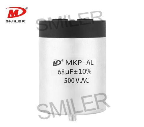
For reactive power compensation, power systems, energy storage equipment, and low-voltage parallel circuits, SMILER capacitor offers the Power Capacitor AC Filter Capacitor MKP-AL. We treat this as a power-filtering example rather than a universal series high-pass component: final selection must follow the intended topology, voltage, current stress, and harmonic spectrum.
A: A series capacitor has high reactance at low frequency, so circuit current and voltage across the load are reduced. As frequency increases, reactance falls and more signal reaches the load.
A: No. A first-order capacitor filter attenuates frequencies progressively. The cutoff is the -3 dB reference point, while signals farther below it receive increasingly greater attenuation.
A: Raising capacitance decreases capacitive reactance at a given frequency. This change also reduces the RC cutoff. As a result, lower-frequency signals can get to the load. They arrive with less attenuation.
A: Yes. The placement in the circuit and the output node decide the response. A series capacitor with output across the load forms a high-pass network. A shunt capacitor commonly forms a low-pass network.
A: Designers should examine capacitance. They must review the effective source and load resistance. Cutoff frequency needs attention. Tolerance is important. Peak voltage requires review. Ripple current should be considered. Temperature matters. ESR and ESL need review. Dielectric suitability must be confirmed.
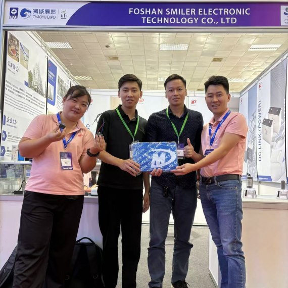
2024 VIETNAM INTERNATIONAL ELECTRONICS & SMART APPLIANCES EXPO
Exploring How AC Capacitors and DC Capacitors Function Differently
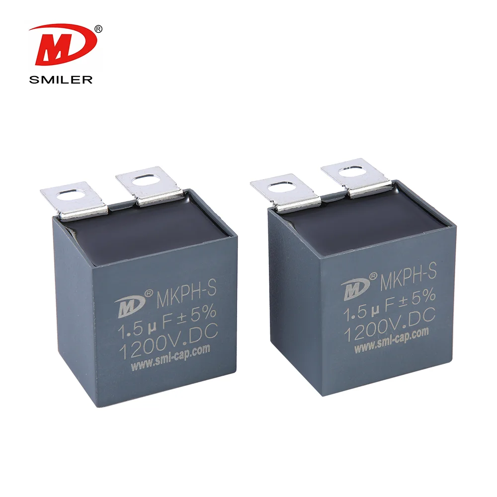
Understanding Snubber Capacitor: RC vs. RCD Snubber Differences
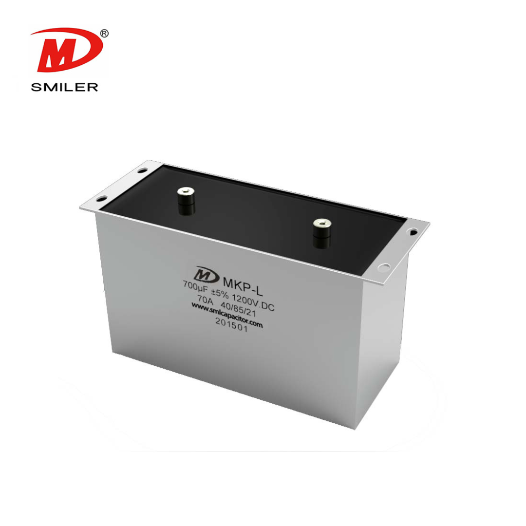
Understanding DC Capacitance to Prevent Converter Oscillations
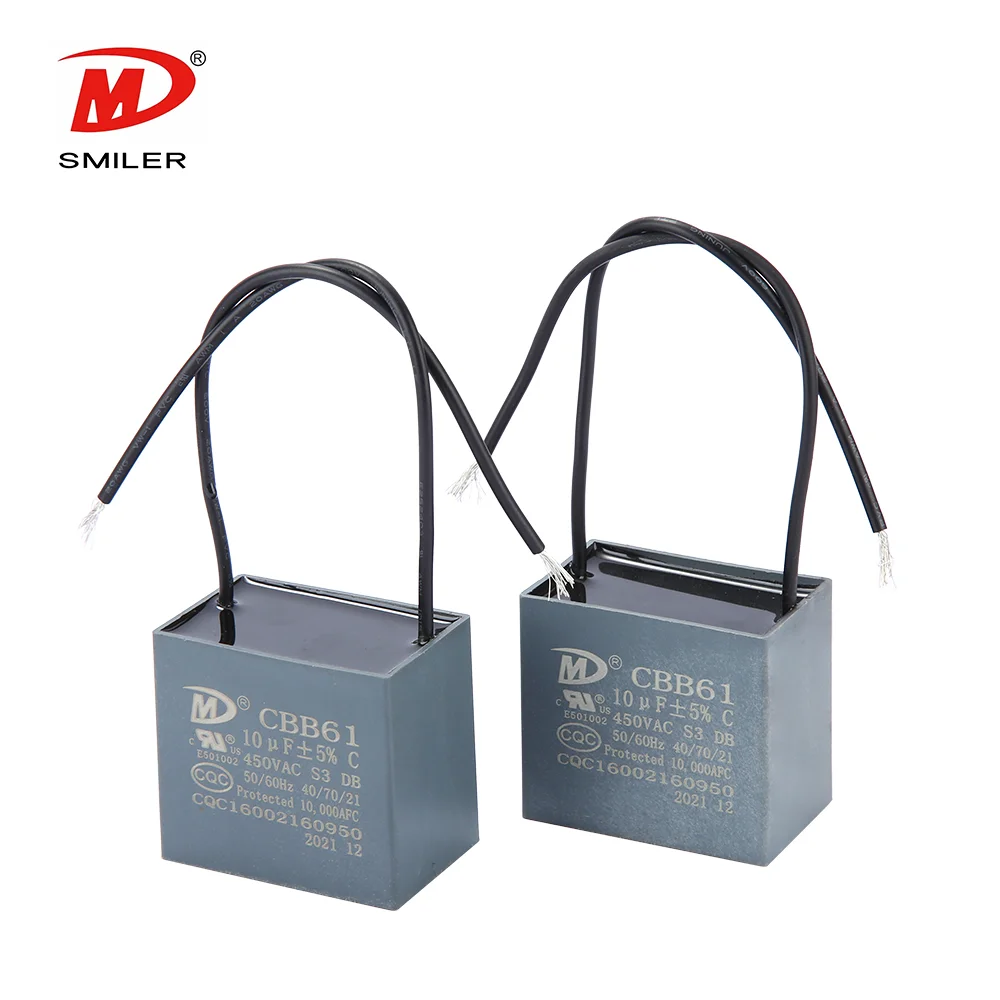
What Does a CBB61 Fan Capacitor Do? Exploring the Role of CBB61 Fan Capacitors


 Add
Building 12,Huazhi Technology Innovation Center,28 Sanle East Road,Beijiao,Foshan,Guangdong,China
Add
Building 12,Huazhi Technology Innovation Center,28 Sanle East Road,Beijiao,Foshan,Guangdong,China
 Phone
+86 18007576965 / 0757-22391591
Phone
+86 18007576965 / 0757-22391591
 Email
ari@sml-cap.cn
Email
ari@sml-cap.cn



