

Picking the capacitor in a switching-node snubber starts with the waveform, not the package outline. The resistor-capacitor-diode branch has to take a repeatable share of switching energy, calm ringing, and tolerate thousands of fast pulses. An MLCC may work in a small, low-energy circuit. When pulse current, voltage stress, and capacitance stability matter over time, a dedicated film part is usually easier to qualify.
An RCD snubber puts a capacitor, resistor, and diode around a switch or transformer winding. As the voltage changes quickly, the capacitor takes in part of the leakage-inductance energy. The diode defines the charging route; the resistor turns that stored energy into heat between switching events. Done well, the branch lowers overshoot and ringing that would otherwise raise EMI, semiconductor stress, or unwanted coupling into a gate and control circuit.
That means the capacitor sees repetitive pulse current, not just a smooth AC waveform. Capacitance, rated voltage, peak-pulse capability, dissipation factor, insulation, thermal behavior, and long-term stability all belong on the checklist. A static calculation may point to the right value while the real component overheats internally or loses too much capacitance at operating voltage.
For a first estimate, designers relate snubber energy to effective capacitance and voltage swing, then choose resistance from the desired damping and average power. Treat that result as a starting point. The measured waveform may include steep dv/dt, parasitic inductance, reverse-recovery current, and more than one ringing frequency. Lead length, mounting inductance, layout, and diode recovery can all change the stress at the capacitor terminals.
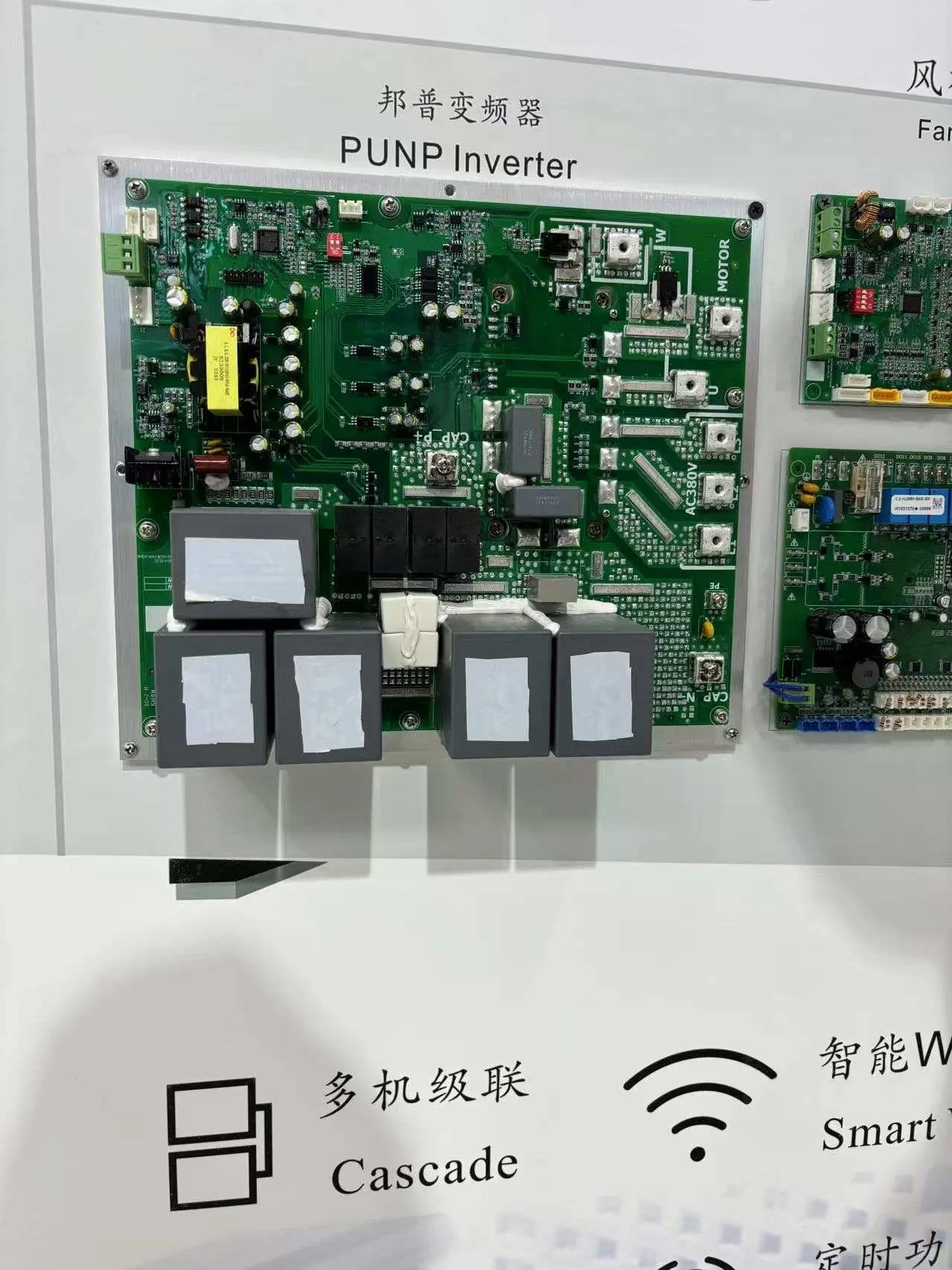
The appeal of an MLCC is straightforward: low ESR, low ESL, tiny dimensions, and strong high-frequency behavior. That combination suits very fast, low-energy spikes close to a semiconductor die or a compact switching loop. A small body can also help keep the radiating loop area down.
The trade-off is that ceramic behavior depends heavily on details that are easy to miss. Check dielectric class, DC-bias derating, aging, mechanical stress, acoustic or piezoelectric effects, and cracking risk. A Class II part can surrender a large portion of its rated capacitance under bias, so a catalog value of 100 nF or 1 µF may not be the value present during the snubber pulse.
An MLCC becomes harder to justify when the RCD branch absorbs meaningful leakage energy on every cycle. Small cases may have little pulse-energy headroom, and the ceramic body can react badly to board flex or mounting stress. Low parasitic inductance is valuable, but it does not by itself prove surge endurance, insulation reliability, or capacitance stability.
High-voltage work adds creepage, clearance, series-stacking, voltage-sharing, and failure-mode questions. A capacitor can pass a low-power bench test and still fail after thermal cycling or repeated overvoltage.
Factor | Dedicated film snubber capacitor | MLCC |
Capacitance stability | Generally stable over voltage and temperature | Depends strongly on dielectric and DC bias |
Pulse-energy suitability | Often designed for repetitive pulse service | Must be verified for the exact waveform |
High-frequency impedance | Low enough for many power-switching loops | Very low ESR and ESL |
Mechanical sensitivity | Usually less vulnerable to board flex | Ceramic cracking can be a concern |
Package size | Larger in many equivalent-energy designs | Very compact |
Main design check | dv/dt, peak current, thermal and insulation stress | DC bias, aging, cracking, pulse and voltage derating |
The practical decision should start with the switching waveform. Measure the peak voltage, ringing frequency, pulse width, repetition rate, and temperature at the mounting location. Then calculate or measure capacitor RMS current and average dissipation. If the component is expected to absorb substantial energy repeatedly, a film snubber capacitor usually provides a wider and more transparent design margin.
In inverter application planning, a DC-link capacitor is assigned to DC filtering and smoothing, while a snubber capacitor is assigned to snubber and IGBT protection. A centralized photovoltaic inverter matrix pairs the MKP-LL Series with the DC-link role and the MKPH-S Series with the snubber role. It lists the MKP-LL Series at 170 µF to 2200 µF and 600 V to 1500 Vdc, while the MKPH-S Series is listed at 0.1 µF to 4.0 µF and 850 V to 2000 Vdc. These ranges show why a bus-energy capacitor and a local transient capacitor should be evaluated as separate parts of the power stage, even when both are film capacitors.
A high-voltage variable-frequency inverter matrix also pairs the MKPH-S Series with snubber and IGBT protection.
The same matrix separates an AC-filter role for output filtering from both DC-link filtering and snubber protection. It pairs that role with the MKP-AL Series and lists 3 × 8 µF to 3 × 335 µF at 230 V to 850 Vac. This reinforces the need to match capacitor selection to the electrical job performed in the converter.
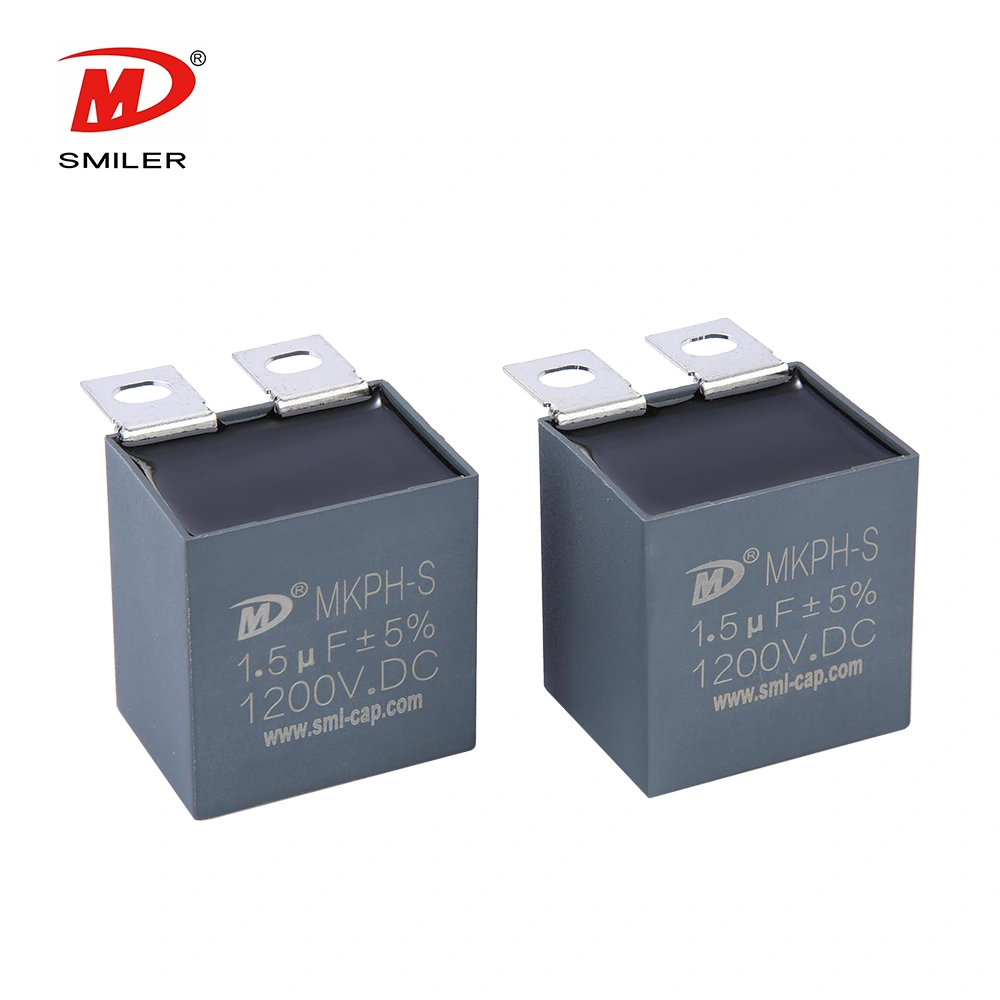
SMILER capacitor supplies film capacitor families for power electronics, including dedicated snubber products for switching and IGBT protection. Its MKPH-S snubber capacitor is a relevant reference point for engineers evaluating a film construction in this role.
Our team can support engineers who need a film-capacitor solution matched to the electrical and mechanical demands of a switching assembly.
The knowledge-base application matrix identifies the MKPH-S Series for snubber and IGBT protection, with a nominal capacitance range of 0.1 µF to 4.0 µF and a voltage range of 850 V to 2000 Vdc. These values are a product-family reference, not a substitute for checking the exact part number, waveform, mounting arrangement, and qualification requirements.
Start with a conservative capacitance and resistor combination based on measured ringing. Verify the switch-node peak voltage with a properly compensated probe, then check capacitor temperature during the highest-load and highest-frequency operating points. Confirm that the resistor's pulse rating and average power rating are both adequate. Finally, repeat the test across input voltage, load, ambient temperature, startup, shutdown, and fault-recovery conditions.
For inverter designs, the capacitor should be reviewed with the complete commutation path. The DC-link loop, switch package, busbar, diode or synchronous device, and snubber mounting position all affect the result. A theoretically suitable component can perform poorly if it is mounted far from the switching loop or connected with long, narrow conductors.
For a broader view of the bus-side component, see the DC-link capacitor product category. It should be evaluated separately from the local RCD branch because its filtering and smoothing duty is different from the snubber's transient-damping duty.
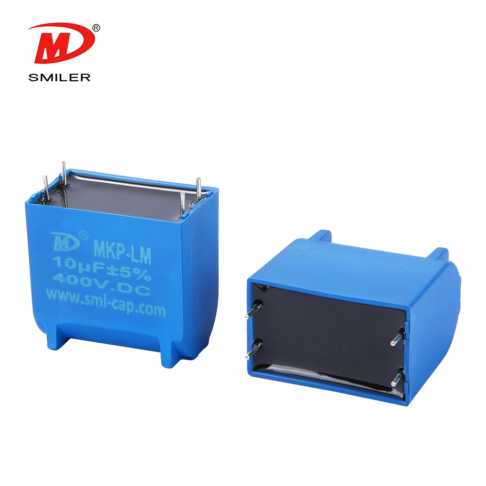
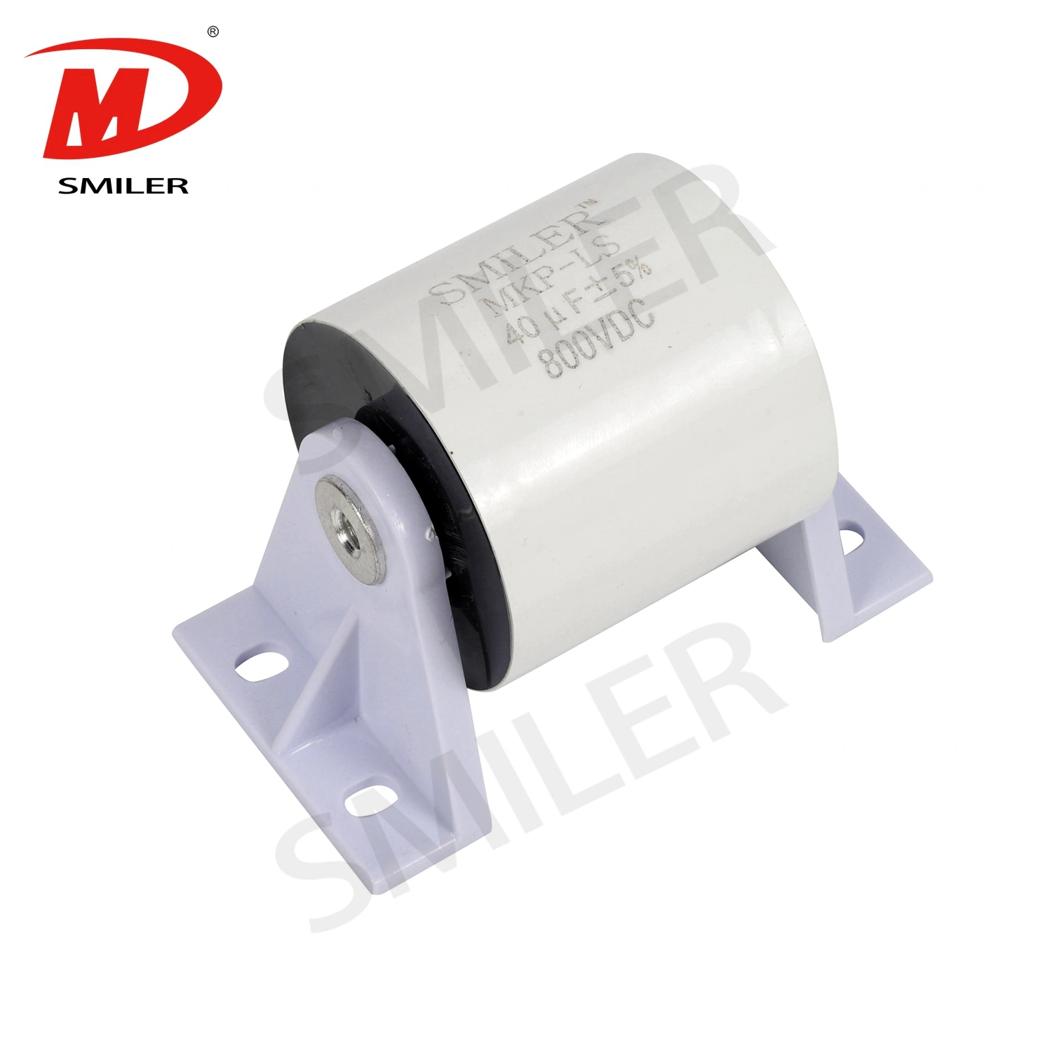
When an application needs a defined high-voltage margin and repeatable pulse behavior, the MKPH-LS snubber capacitor is another product family to evaluate. The final choice should use the manufacturer's exact electrical data and the measured application waveform rather than a generic comparison table.
A DC-link capacitor and an RCD snubber solve different problems: the former supports bus energy and ripple management, while the latter limits local switching transients. Treating them as interchangeable can lead to incorrect capacitance, voltage, or lifetime assumptions.
A: An RCD snubber capacitor is chosen for repeated pulse energy. It also considers voltage stress. It accounts for thermal behavior in a damping network. An MLCC is a small ceramic component. It has very good high frequency impedance. But its capacitance and mechanical reliability may shift more. This occurs with DC bias. It depends on dielectric choice. Board stress affects it as well.
A: It can work in some low-energy applications. These also have low voltage. The circuits are tightly optimized. Yet any replacement needs careful checks. You must examine the waveform. Pulse current needs testing. You should verify capacitance under bias. Temperature effects matter. Lifetime testing is necessary. Matching only the nominal capacitance is not enough.
A: The capacitor charges and discharges often. This takes place as the switching node changes state. Leakage inductance adds to the stress. Reverse recovery current increases it further. Parasitic inductance contributes too. Ringing creates additional problems. These elements can cause high peak current. They also produce high voltage. This happens even when average circuit power seems low.
A: A dedicated film snubber capacitor usually offers a better starting choice for IGBT protection. The design can focus on pulse capability. It can emphasize insulation. Stable capacitance is another key factor. Still the right selection depends on the IGBT topology. It varies with switching frequency. Voltage margin is important. The layout plays a role. You must consider measured transients.
A: Begin by measuring the actual switching waveform. Then estimate the stored energy. Also calculate the dissipated energy. Check the limits for repeated pulses. Verify the thermal limits next. Test the whole assembly under different voltages. Do the same for various loads. Include different temperatures. Add fault conditions to the tests. Finally, compare these real requirements. Use the capacitor datasheet for this. Review the qualification evidence too.
RCD Snubber Capacitor Selection: Measures for Surge Suppression
RCD Snubber Capacitor vs RC Snubber: Key Performance and Design Insights

How RCD Snubber Capacitors Reduce EMI in Power Electronics

Best RCD Snubber Capacitor: Top 5 Choices for 2026
Top RCD Snubber Capacitor Types for 2026 Inverters


 Add
Building 12,Huazhi Technology Innovation Center,28 Sanle East Road,Beijiao,Foshan,Guangdong,China
 Phone
+86 18007576965 / 0757-22391591
 Email
ari@sml-cap.cn



