

Half-wave rectification blocks one half of the sine wave. Full-wave bridge rectification converts both halves to positive. As a result, the output polarity no longer alternates. However, the voltage still rises and falls.
For a sine-wave source, begin with this.
Vpeak ≈ VRMS × 1.414
An ideal 12 V AC RMS source reaches about 17.0 V at its peak. A lightly loaded transformer may sit above its nameplate voltage.
A half-wave path contains one conducting diode. A bridge path contains two.
VDC(no-load) ≈ VRMS × 1.414 − n × VF
Here n is the conducting-diode count, and VF is each diode's forward drop. Device type, current, and temperature affect that drop.
Winding resistance, transformer regulation, and diode loss pull the voltage down as current rises. No-load readings can approach the calculated peak. Under load, the average is lower, and ripple is deeper.
The capacitor creates no voltage. When the waveform rises above its stored level, the rectifier conducts and charges it. As the source falls, conduction stops. The meter then reads a level held near the crest.
Between peaks, stored energy feeds the load. Voltage slopes downward instead of collapsing toward zero. It rises at the next charge. Load current, capacitance, and the interval set the ripple depth.
The numbers describe different quantities. For 12 V AC, the ideal crest is 12 × 1.414 = 17.0 V. Two bridge-diode drops may leave about 15.5 to 16 V at light load. Mains, regulation, and load make the result vary.
A heavier load empties the capacitor faster. More capacitance slows the fall. With a steady load, doubling capacitance roughly halves peak-to-peak ripple. Doubling current roughly doubles it. Pulsed loads need closer transient analysis.
Half-wave rectification recharges once per AC cycle. A full-wave bridge recharges twice. Thus, 50 Hz produces 100 Hz ripple and 60 Hz produces 120 Hz. The shorter wait reduces required capacitance.
ESR converts the ripple current to heat. Increased capacitance can cause the voltage to go down and create larger pulses during recharge. The pulses place a strain on the capacitor, the rectifier, and the transformer.
Use the maximum continuous load and acceptable peak-to-peak ripple. The ripple valley must stay above the regulator dropout or a controller's minimum input. Design for low line and high load.
For a first-pass value, use this.
C ≈ Iload / (fripple × ΔV)
Iload is amperes. fripple is hertz. ΔV is peak-to-peak ripple in volts. C is farads. Further capacitor filter calculations for power supplies still require allowance for tolerance, temperature, and source impedance.
With half-wave rectification, ripple normally equals the AC frequency. At 0.2 A, 50 Hz, and 1 V of allowable ripple, the result is this.
C ≈ 0.2 / (50 × 1) = 0.004 F = 4,000 µF
Choose a standard value with tolerance and aging margin.
On a 50 Hz supply, a full-wave bridge gives fripple = 100 Hz.
C ≈ 0.2 / (100 × 1) = 0.002 F = 2,000 µF
The doubled recharge rate halves the calculated capacitance for this target.
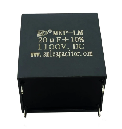
Voltage rating must clear the highest credible no-load peak. This includes high mains, regulation, and transients. Ripple-current and temperature ratings must fit the enclosure. For higher-voltage buses, SMILER capacitor supplies DC-link film products for filtering and smoothing. Our Power Capacitor DC Link Capacitor MKP-LM (THB-Type) serves renewable-energy and industrial conversion equipment. Selection still follows actual electrical and thermal demands.
Undersizing creates deep ripple valleys. A regulator can drop out. A controller may reset. A display may flicker. Audio equipment may hum as load rises.
More is not automatically safer. An empty oversized capacitor draws high inrush. It concentrates normal charging into short pulses. Diodes, windings, switches, and fuses must tolerate the current.
Overvoltage can damage the dielectric. It can raise leakage and shorten life. Polarized parts need correct polarity. The technology must also suit ripple current, frequency, temperature, and lifetime.
In a line-frequency supply, it is usually a reservoir capacitor. It charges near each peak and supports the load between peaks. Selection covers voltage, ripple current, inrush, polarity, and temperature as well as capacitance.
In power electronics, the post-rectifier position is often called a DC link. Its assigned task is DC filtering and smoothing between conversion stages. A snubber is a separate component used for IGBT protection. An AC-filter capacitor works at the output. Their circuit jobs are not interchangeable.
Commercial energy-storage inverters assign the MKP-LM Series to DC filtering and smoothing. They use a separate snubber for IGBT protection. They use an MKP-AM Series capacitor for output filtering.
Distributed solar inverters use the same division. They place MKP-LM at the DC link. They use a dedicated snubber at the switching stage. They use MKP-AM at the output.
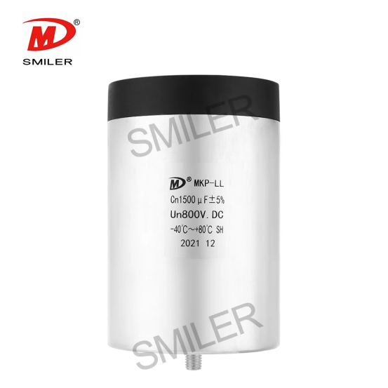
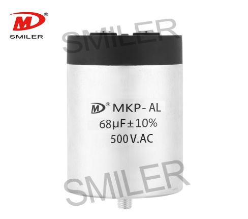
Central solar converters instead assign the MKP-LL Series to DC filtering and smoothing. They assign the MKPH-S Series to snubber protection. They assign the MKP-AL Series to output filtering.
Wind power converters use that MKP-LL, MKPH-S, and MKP-AL arrangement for the same three roles. Medium- and high-voltage frequency converters use an MKP-LL Series DC-link capacitor for filtering and smoothing together with an MKPH-S Series snubber for IGBT protection.
In HEV and EV onboard chargers, automotive-grade across-the-line capacitors are separated from the DC-link part used for filtering and smoothing. A distinct high-voltage resonant or snubber capacitor serves the switching section. Those parts should not be treated as interchangeable.
For demanding buses, the Power Capacitor DC Link Capacitor MKP-LL is intended for renewable-energy inverters, industrial drives, and traction applications. It is not a drop-in choice for a small supply. The converter dictates voltage, ripple current, ESR, mounting, and thermal limits.
A reservoir or DC-link capacitor smooths but does not regulate voltage. A regulator improves accuracy. An LC stage or local high-frequency decoupling can reduce remaining noise.
A: It charges toward the waveform peak. AC sources are rated in RMS volts. Stored DC can exceed the AC nameplate value after diode losses.
A: Start with Vpeak ≈ VRMS × 1.414. Subtract conducting-diode drops. Then allow for transformer regulation, source resistance, load, and ripple.
A: Begin with C ≈ Iload / (fripple × ΔV). Then check voltage, ripple-current capability, temperature, tolerance, aging, and lifetime.
A: No. It loses charge while supporting the load between peaks. More capacitance reduces ripple. Regulation or another filter may still be needed.
A: Choose above the highest expected no-load peak. This includes mains tolerance, transformer regulation, transients, temperature derating, and the manufacturer's margin.
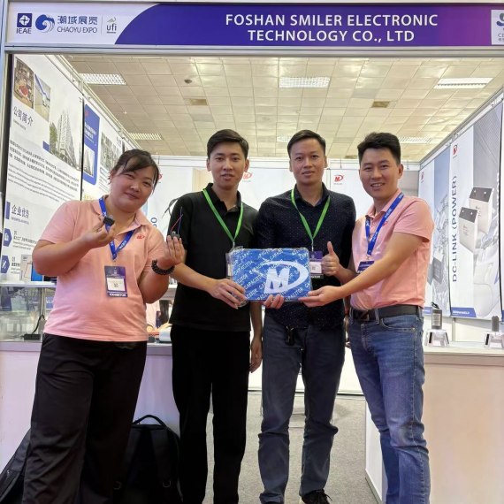
2024 VIETNAM INTERNATIONAL ELECTRONICS & SMART APPLIANCES EXPO
Exploring How AC Capacitors and DC Capacitors Function Differently
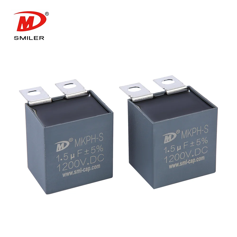
Understanding Snubber Capacitor: RC vs. RCD Snubber Differences
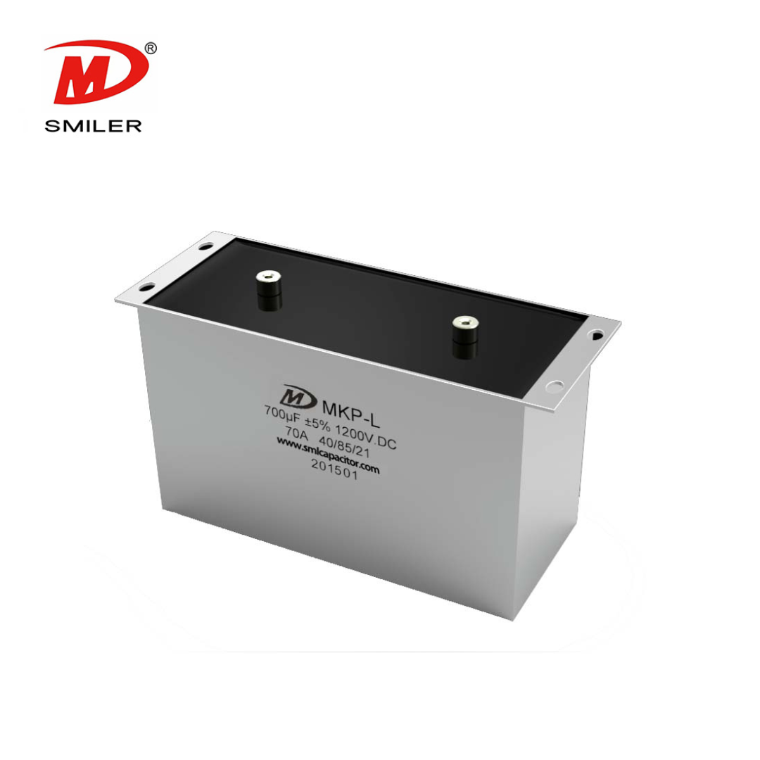
Understanding DC Capacitance to Prevent Converter Oscillations
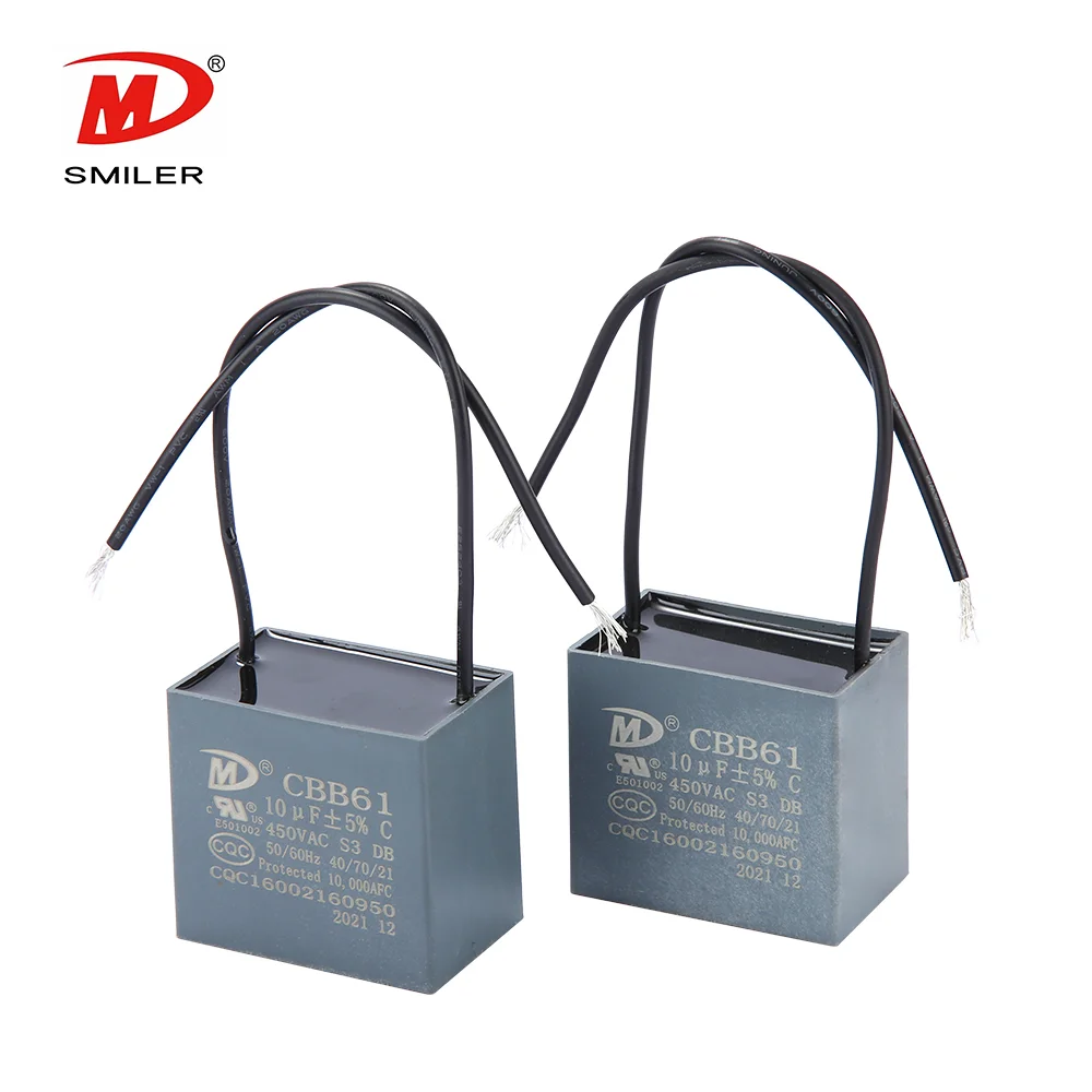
What Does a CBB61 Fan Capacitor Do? Exploring the Role of CBB61 Fan Capacitors


 Add
Building 12,Huazhi Technology Innovation Center,28 Sanle East Road,Beijiao,Foshan,Guangdong,China
Add
Building 12,Huazhi Technology Innovation Center,28 Sanle East Road,Beijiao,Foshan,Guangdong,China
 Phone
+86 18007576965 / 0757-22391591
Phone
+86 18007576965 / 0757-22391591
 Email
ari@sml-cap.cn
Email
ari@sml-cap.cn



