

Optimizing DC link capacitor design for 3-phase inverter efficiency is a critical engineering task because the DC bus directly influences voltage stability, power loss distribution, and long-term system reliability. In modern three-phase inverter applications, the DC link capacitor is not a passive supporting component but a functional element that shapes inverter efficiency, thermal behavior, and operational stability. A well-optimized DC link design reduces ripple stress, supports fast switching, and enables stable performance under dynamic load conditions.
DC link capacitor design for 3-phase inverter systems determines how effectively energy is buffered between the rectifier stage and the inverter bridge. The DC bus capacitor smooths pulsating input power and absorbs current fluctuations generated by three-phase switching actions, directly influencing voltage stability and device stress.
In practical inverter applications, insufficient DC bus energy storage often leads to excessive voltage ripple, higher RMS current stress on power devices, and increased thermal losses. Proper DC link design ensures balanced energy flow during transient events such as motor acceleration or regenerative braking.
DC Link Capacitor design for 3 phase inverter efficiency grows more vital as switching speeds climb and inverter power pack rises. Current factory drives, renewable energy inverters, and traction setups need steady DC bus action under fast current shifts.

If the DC link impedance sits too high, switching losses go up. EMI gets tougher to manage. A low-impedance DC link keeps voltage waveforms clear. It cuts switching strain. And it backs a higher overall system efficiency.
Equivalent series resistance is a key parameter in DC link capacitor design for 3-phase inverter efficiency because it determines conduction losses caused by ripple current. High ESR results in higher internal temperature rise and accelerated aging.
In real operating conditions, ripple current varies with load and switching behavior. A DC link capacitor with low ESR can handle these variations with minimal loss, helping stabilize inverter temperature and extend service life.
Picking the voltage rating forms a basic step in DC link capacitor design for 3 phase inverter uses. The DC bus needs to handle normal voltage, short overvoltage, and ongoing strain in high heat.
Right voltage derating keeps capacitance and ESR steady over time. Engineers check the voltage room along with the heat states. This avoids efficiency drop from wear-based shifts in parameters.
Parasitic inductance strongly affects DC link capacitor design for 3-phase inverter efficiency in high-frequency switching environments. Excessive inductance can cause voltage overshoot, ringing, and increased EMI.
Reducing loop inductance through capacitor structure and layout optimization improves switching waveform quality and reduces stress on power semiconductors, especially in IGBT- and SiC-based inverter platforms.
Capacitor technology choice has a direct impact on DC link capacitor design for 3-phase inverter efficiency. Electrolytic capacitors offer high capacitance density but typically have higher ESR and limited lifetime.
Film capacitors provide lower ESR, better ripple current handling, and longer service life, making them more suitable for high-efficiency inverter systems. Hybrid capacitor banks are sometimes used to balance performance and size constraints.
Metallized polypropylene film sees wide use in DC link capacitor design for 3 phase inverter efficiency. It offers low dielectric loss, self-healing ability, and steady long-term work.
These traits suit polypropylene film capacitors for factory drives, photovoltaic inverters, and electric vehicle power parts. There, efficiency and dependability matter most.
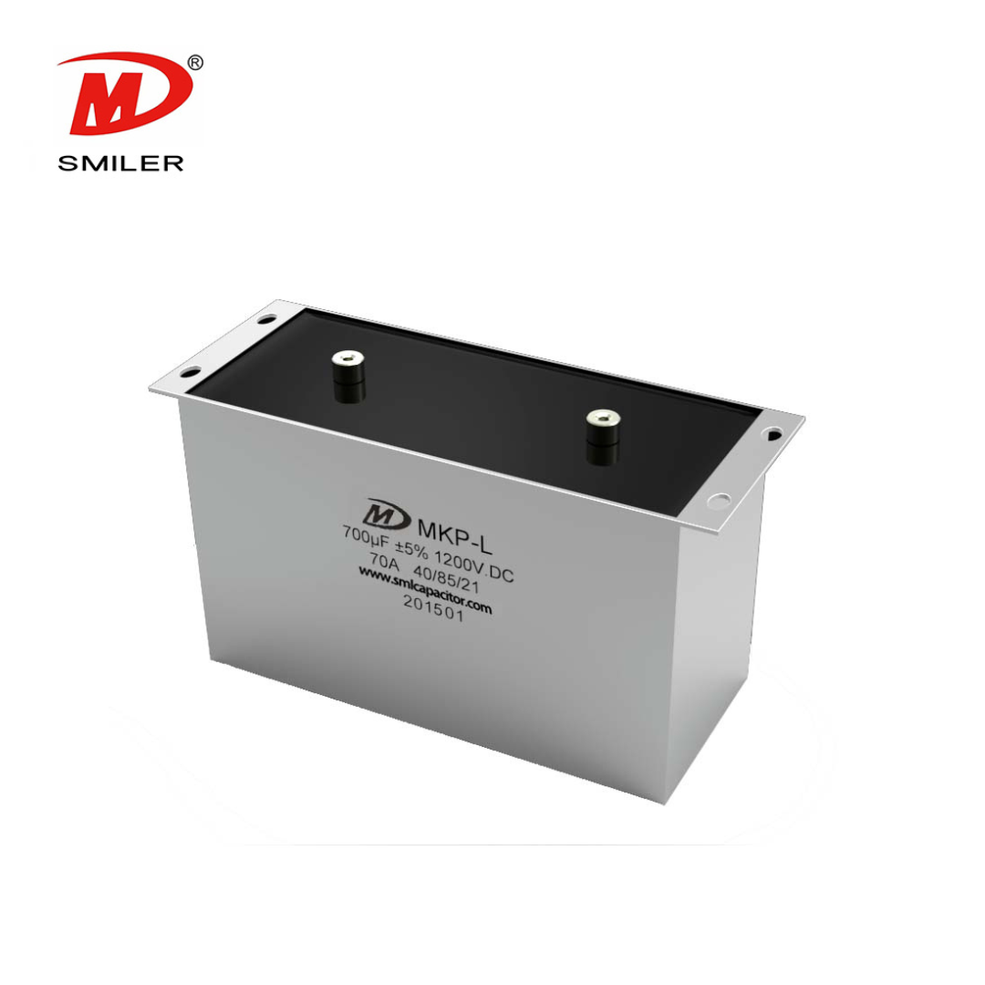
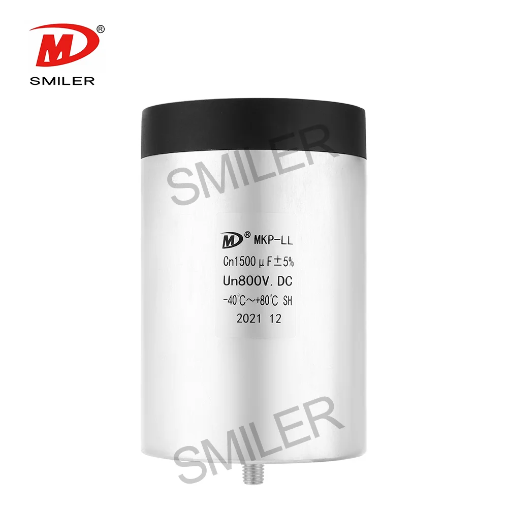
Mechanical structure significantly influences thermal performance in DC link capacitor design for 3-phase inverter systems. Aluminum case designs typically offer improved heat dissipation, while plastic case designs allow compact installation and flexible mounting.
Effective thermal paths prevent localized overheating and help maintain stable electrical characteristics under continuous operation.
DC link capacitor design for 3-phase inverter systems must account for dynamic load behavior that introduces fluctuating electrical stress. Repeated current transients during acceleration or braking contribute to gradual parameter changes over time.
Proper selection of ripple current capability, voltage margin, and thermal stability helps maintain efficiency throughout the inverter's service life.
Setting conditions greatly shape the DC link capacitor design for the 3-phase inverter efficiency. High moisture, high surrounding heat, and long run hours speed up wear if materials and seals fall short.
Capacitors in factories and renewable energy inverters need to hold electrical power. They must resist dampness, heat shifts, and mechanical shakes.
Proper sizing is essential in DC link capacitor design for 3-phase inverter efficiency. Oversizing increases cost and footprint, while undersizing leads to excessive ripple and reduced efficiency.
Optimized layout reduces parasitic inductance and resistance, improving DC bus performance without increasing component count.
Layout design directly affects DC link capacitor performance in high-frequency inverter systems. Minimizing loop area between the capacitor and power devices reduces inductive voltage spikes and switching losses.
Strategic integration of DC link capacitors improves efficiency, EMI performance, and overall system robustness.
SMILER capacitor supports DC link capacitor design for 3-phase inverter efficiency through application-oriented evaluation of voltage range, ripple current profile, temperature conditions, and lifetime expectations.

This approach helps inverter manufacturers achieve stable performance without unnecessary overdesign.
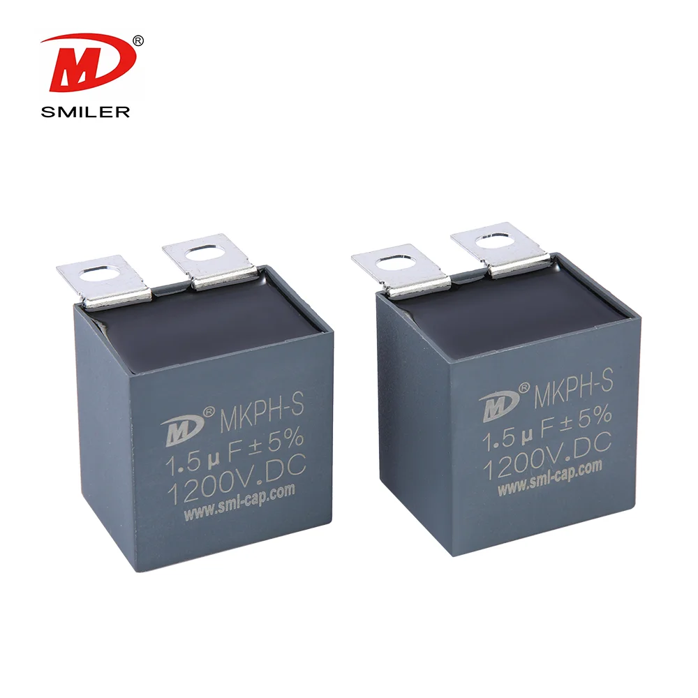
SMILER capacitor offers metallized polypropylene film DC link capacitors designed for low ESR, high ripple current capability, and long operational life. Typical solutions include aluminum case dry-type DC link capacitors and plastic case pin-type DC link capacitors used in industrial drives and renewable energy inverters.
In practical inverter projects, these capacitors have been applied in three-phase motor drive systems where stable DC bus voltage and controlled thermal rise were required, resulting in consistent long-term operation.
Engineering validation and quality control ensure that SMILER capacitor solutions meet performance expectations before deployment. Electrical testing, thermal evaluation, and reliability verification help inverter manufacturers achieve predictable efficiency and long-term stability.
A: A good brand focuses on low ESR, high ripple current capability, stable thermal behavior, and proven long-term reliability rather than capacitance value alone.
A: Metallized polypropylene film capacitors are commonly recommended due to their low loss, strong ripple current handling, and long service life.
A: Selection should consider operating voltage, ripple current, ambient temperature, expected lifetime, and layout constraints together.
A: Film capacitors generally offer better efficiency and lifetime, while electrolytic capacitors may be used when high capacitance density is required.
A: Companies with strong experience in metallized film capacitor manufacturing, application-specific customization, and quality control are typically preferred.
Understanding Snubber Capacitor: RC vs. RCD Snubber Differences

Understanding DC Capacitance to Prevent Converter Oscillations
Exploring the Role of DC Link Capacitor Use in EV Power Systems
Understanding Why Capacitors Pass AC but Block DC in Circuits
RC vs. RCD Snubber: Key Differences and Applications Explained


 Add
Building 12,Huazhi Technology Innovation Center,28 Sanle East Road,Beijiao,Foshan,Guangdong,China
Add
Building 12,Huazhi Technology Innovation Center,28 Sanle East Road,Beijiao,Foshan,Guangdong,China
 Phone
+86 18007576965 / 0757-22391591
Phone
+86 18007576965 / 0757-22391591
 Email
ari@sml-cap.cn
Email
ari@sml-cap.cn


