

The placement of a DC blocking cap is vital. It shapes the circuit's ability to stop unwanted DC parts while letting AC signals pass. If the capacitor is placed incorrectly, it may not block DC bias well. This can cause signal distortion or issues in later stages. For example, placing it too far from the signal source or in a bad spot leads to problems.
Wrong placement can link circuit parts in unwanted ways. For instance, if placed downstream instead of at the input, leftover DC voltage may flow into sensitive analog or RF stages. This could overload amplifiers or shift operating points. Such errors often lower system performance. They may also cause unpredictable actions.
DC blocking caps play a key role in keeping signals clear. They separate DC levels between circuit stages. Proper placement ensures only the desired AC signals move through. It also stops ground loops and voltage offsets. Placing caps near the signal source or load cuts parasitic inductance. This reduces noise pickup.
In fast or high-frequency systems, even small placement errors can cause issues. They may lead to impedance mismatches, signal reflections, or electromagnetic interference (EMI). This matters a lot in RF systems. Here, phase and amplitude accuracy are crucial for clear communication.
Several frequent mistakes can weaken DC blocking caps. One common error is placing the capacitor too far from connectors or transmission lines. This increases trace length and inductive reactance. Another issue is ignoring the return path for AC signals. This creates loop areas that act as EMI antennas.
Also, using capacitors with wrong values or traits, like high ESR (Equivalent Series Resistance), can lower filtering power. Designers should avoid placing blocking caps across power supply rails unless needed for decoupling tasks.

In high-frequency setups like RF transceivers and microwave systems, DC blocking caps are essential. They keep signal clarity and prevent interference between stages with different bias voltages. Their main job is to allow fast AC shifts while blocking static voltage parts.
To work well, capacitors with low ESR and minimal parasitic inductance are best. DC Filtering and Smoothing Snubber, IGBT Protection Output Filter capacitors have similar roles. They manage short-term energy and keep waveforms clear at switching points.
In audio systems, the wrong placement of a DC blocking cap can cause low-frequency loss or phase distortion. This happens due to impedance mismatches between stages. In RF systems, bad positioning can detune resonant circuits or raise insertion loss.
Capacitor choice must match frequency needs. For example, ceramic capacitors suit RF paths due to low inductance. But they may affect audio signals poorly compared to film types.
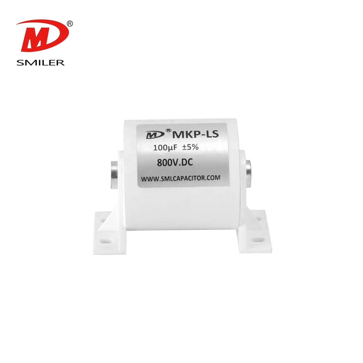
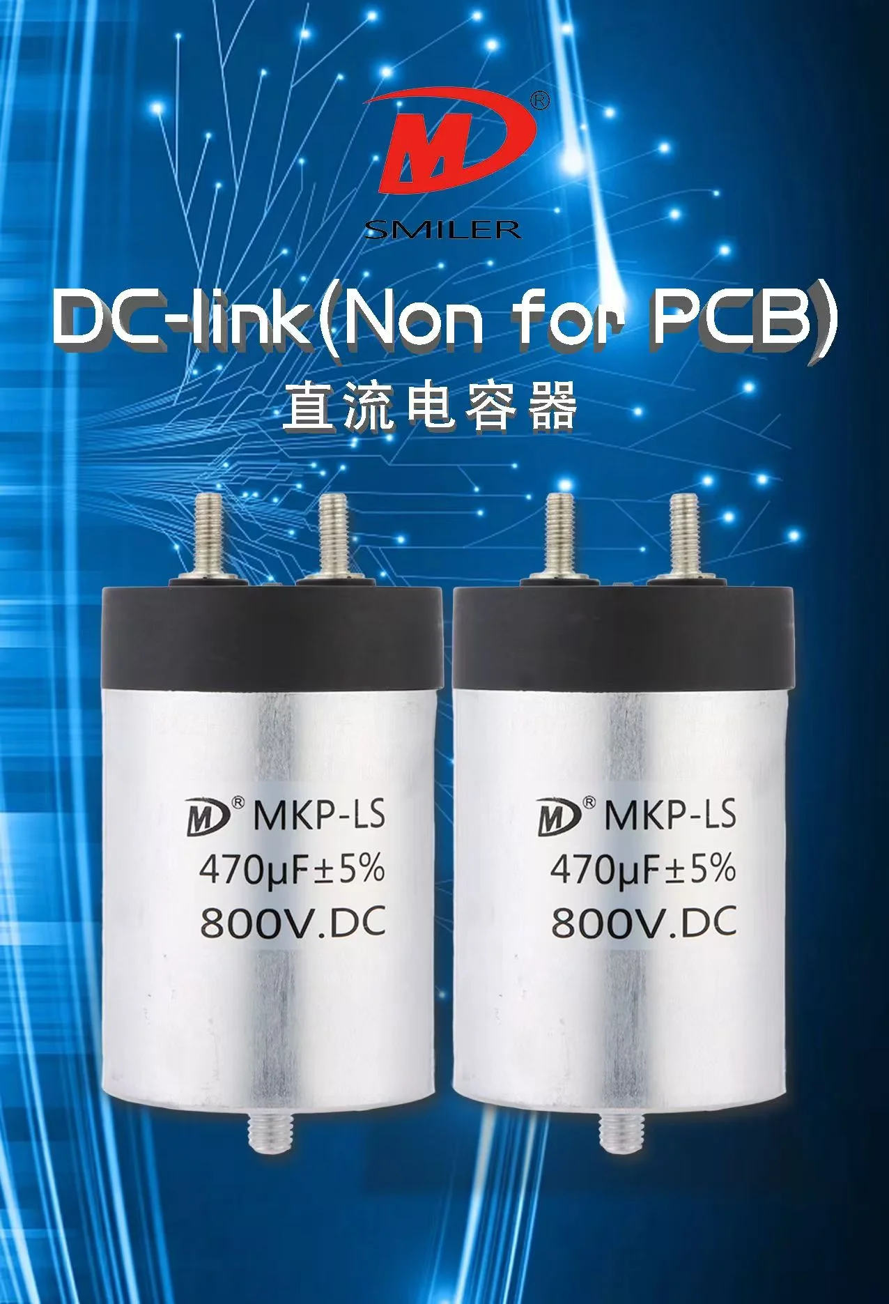
While not typically used as blocking parts in power lines, similar rules apply for isolation or filtering capacitors. DC Link Capacitor setups are often placed near power semiconductors like IGBTs. They maintain steady voltage levels during switching events.
DC Filtering and Smoothing Snubber, IGBT Protection capacitors must sit close to switching devices. This helps suppress voltage spikes well and keeps thermal balance across parts.
Wrongly placed blocking capacitors can expose downstream parts to unwanted voltages. This risk grows with active devices like op-amps or transistors. These have strict biasing needs. Voltage leaks from poor isolation can cause saturation, breakdowns, or odd behavior.
If a capacitor fails open due to stress from placement near high-energy points, it may stop blocking DC. This harms circuit protection fully.
Thermal control ties closely to capacitor placement. A poorly aired spot near heat-making parts can speed up dielectric wear in the capacitor. Over time, this leads to changed capacitance values or higher ESR. Both hurt system reliability.
DC Link Capacitor uses face ongoing stress from ripple current and voltage swings. They need strong thermal traits to stay reliable.
Yes, especially in high-voltage setups with tight safety margins. Wrongly placed capacitors might create short-circuit paths during board flexing or thermal expansion. In industrial settings with motor drives or converters using Snubber Capacitor technology, a bad layout can cause insulation failures. These pose electrocution risks or equipment damage.
The best spot for a DC blocking cap is right before an interface needing an AC signal flow but with differing DC levels. Examples include between amplifier stages or at antenna inputs/outputs. Placing it close reduces parasitic effects. It also ensures strong decoupling of voltage zones.
Designers should use tools like SPICE and impedance analysis, such as Smith charts. These help find the best spots based on frequency response and system design.
Capacitor pads should stay close to related traces. Avoid stubs that harm transmission line clarity. Ground planes must provide low-resistance return paths. These should align directly under signal layers carrying AC currents through the cap.
Avoid routing sensitive analog signals near high-current digital lines. This prevents noise coupling into the path guarded by the blocking cap.
Smart placement considers electrical distance (impedance) and physical closeness (trace length). For example, placing a cap right after an output buffer keeps load conditions steady. This matters in modular designs like sensor interfaces or communication units, despite downstream changes.

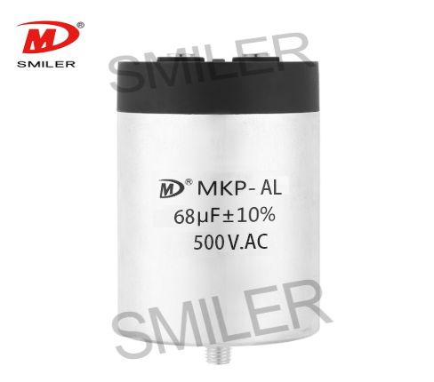
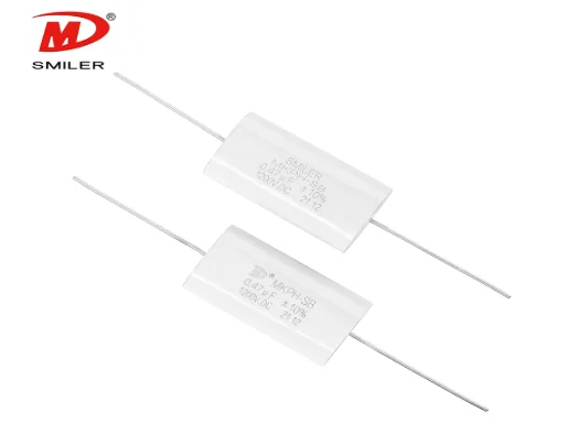
SMILER is a professional film capacitor maker based in Foshan, Guangdong. We focus on crafting high-performance capacitors for industrial electronics, renewable energy systems, consumer products, and more.
Our product range includes DC-Link Capacitor, Snubber Capacitor, AC-Filter Capacitor, and CBB Capacitor. All are built with precise engineering standards that meet global compliance rules.
SMILER's film capacitors have very low ESR values. This makes them great for high-frequency setups like RF communication systems and power conversion modules. Fast transient response is key in these uses.
With tight capacitance tolerances across temperature ranges, SMILER capacitors give steady performance across batches. This predictability is vital in automated control systems where safety depends on consistency.
We use advanced metallized polypropylene films. These offer strong self-healing and resist dielectric breakdown. With strict lifecycle testing, SMILER's capacitors meet tough global standards for safety and long life.
SMILER's MKP series has been used in base station filters. These need clean signal boundaries across gigahertz frequencies for network uptime. Our capacitors ensure this clarity.
In factory automation with IGBT-based motor drives, SMILER's snubber capacitors were used with protective relays. This cut downtime by improving transient suppression.
Compact CBB series capacitors from SMILER fit into smart home devices. They suit limited board space while keeping reliability over years of daily use.
A: Wrong placement can cause phase shifts and bass loss due to impedance mismatches. Placing caps near stage boundaries with proper values improves sound clarity.
A: Think about capacitance value for the frequency range, ESR for noise control, dielectric type for stress tolerance, and size for PCB layout.
A: Yes, when placed at input/output boundaries between biased circuits, they block harmful DC offsets. This protects sensitive ICs like op-amps or ADCs.
A: SMILER offers a wide range of film-based capacitors built for industrial conditions. These include snubber and DC link types with strong durability.
A: Yes, film capacitors with low ESR, like SMILER's, work well for RF circuits. They offer stable performance over wide frequency ranges without unwanted resonance.
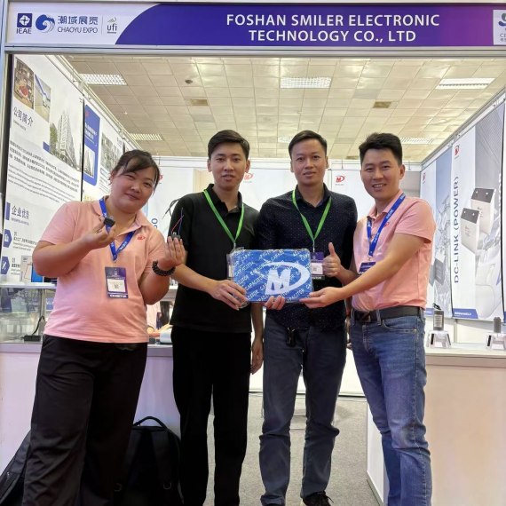
2024 VIETNAM INTERNATIONAL ELECTRONICS & SMART APPLIANCES EXPO
Exploring How AC Capacitors and DC Capacitors Function Differently
What Drives AC Capacitor Cost? A Comparison with DC Capacitors
Snubbing Capacitors in Power Electronics: RC vs. RCD Snubber
Why DC Link Capacitance Matters in Modern Electronics Design?


 Add
Building 12,Huazhi Technology Innovation Center,28 Sanle East Road,Beijiao,Foshan,Guangdong,China
Add
Building 12,Huazhi Technology Innovation Center,28 Sanle East Road,Beijiao,Foshan,Guangdong,China
 Phone
+86 18007576965 / 0757-22391591
Phone
+86 18007576965 / 0757-22391591
 Email
ari@sml-cap.cn
Email
ari@sml-cap.cn


