

Power supply design in industry calls for careful work. One ongoing issue for engineers is removing leftover changes after turning AC into DC. Getting good capacitor ripple reduction goes beyond just picking any capacitor size. It needs a clear grasp of how the circuit works, how parts behave, and how to handle heat.
In power electronics, rectifiers transform alternating current into a unidirectional flow. However, this output is not a perfectly flat line. Instead, it appears as a pulsating sequence of peaks and valleys known as ripple voltage. This residual fluctuation represents the incomplete transition from an alternating waveform to a stable continuous current, highlighting the necessity for dedicated smoothing circuits.
Allowing excessive ripple voltage to pass through a rectified DC power supply can be catastrophic for downstream components. Sensitive microprocessors and logic circuits can experience data corruption or phantom triggering due to unstable voltage logic levels. Furthermore, continuous exposure to these fluctuations generates excess heat within the circuit, accelerating component degradation and drastically shortening the operational lifespan of the entire industrial control system.

A smoothing capacitor works as a quick energy store. When the varying voltage from the rectifier climbs to its top, the capacitor takes in this extra power and charges up. Then, as the rectifier voltage falls back to zero, the capacitor starts to release its stored power to the load. This keeps the voltage steady.
This ongoing process of filling and emptying fills in the spaces between voltage tops. The capacitor adds current right when the rectifier output drops. As a result, it smooths out the deep lows in the wave. How well this capacitor ripple reduction works decides how much the final output looks like a true, even DC source.
Engineers use a basic math step to find the needed capacitance for a setup. For a full-wave rectifier, the formula is C = I / (2 * f * V_ripple). Here, 'I' stands for load current, 'f' is the AC line frequency, and 'V_ripple' is the top allowed peak-to-peak ripple voltage. Doing this right avoids waste from too much size or risk from too little.
The formula gives a starting point. But in real power supply builds, you must match the calculated capacitance to the actual needs of the load current. Bigger currents empty the capacitor quicker in the release phase. This raises the ripple voltage on its own. So, designers pick parts that fit the farad need. They also handle fast power shifts without big voltage falls.

A key point in picking parts is the equivalent series resistance (ESR). It often gets missed. High ESR leads to inside heat from the steady AC ripple. Over time, this heat breaks down the capacitor's build. Thus, parts with very low ESR are preferred. They create less heat and offer a better way to filter quick noise.
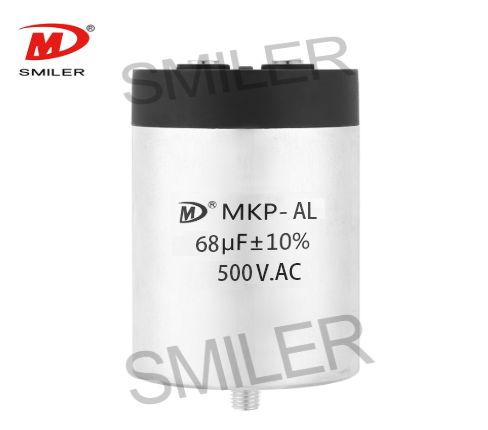
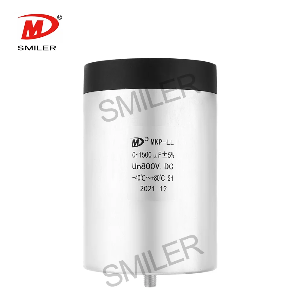
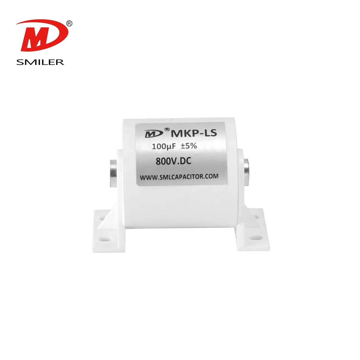
Common aluminum electrolytic capacitors have trouble with steady high currents. Their liquid filler dries out with use. On the other hand, modern film capacitors are made to manage tough loads. In strict industrial power designs, adding a SMILER capacitor, especially our DC Link Capacitors, gives strong current support. The coated film build stands up to heat stress that usually ruins standard parts in heavy use.
Factory and green energy uses need years of non-stop work. Film capacitors last longer than electrolytic ones. They do not depend on drying chemical fillers. Even better, a solid SMILER capacitor has a strong self-healing feature. Small breaks in the insulator get fixed right away by tiny vapor bursts. This lets the part keep working safely without a full short.
Even with optimal component selection, ambient heat remains an enemy of smoothing circuits. Prolonged exposure to high operating temperatures accelerates the degradation of dielectric materials. Engineers must implement adequate spacing, heat sinks, or active airflow around the capacitor banks to ensure the internal core temperature remains well below the component's maximum rated threshold.
How the printed circuit board is set up affects how well the capacitor ripple reduction performs. If smoothing parts sit too far from the rectifier diodes, extra coil effects build up in the traces. This works against the capacitor's power to catch quick voltage jumps. For best results, main storage and small decoupling capacitors go as close as possible to the rectifier bridge and the key load.
A: The top way uses a mix of large DC-Link capacitors for main energy hold and tiny bypass ones for quick noise cut. In big-power factory setups, switching to advanced coated film capacitors boosts handling of high ripple currents. It also keeps a steady rectified DC output.
A: Equivalent series resistance (ESR) shapes the work and heat hold of smoothing circuits. High ESR makes the capacitor heat up inside while taking in and giving out energy. This cuts its filter power a lot. Low ESR parts allow cleaner, better energy flow. They lead to a smoother output line.
A: Electrolytic types give high capacitance in a small space. But film options like a SMILER capacitor rank as the top choice for current, tough uses. They offer very low ESR, endless storage life, and great self-healing. This makes them perfect for capacitor ripple reduction in rough factory settings.
A: To find the smallest needed size, apply the basic formula for your circuit's load. For a full-wave rectifier, divide the steady load current by two times the AC frequency times your allowed ripple voltage. This math makes sure you have enough storage to smooth the wave well.
A: Without proper capacitor ripple reduction, parts later in the line get raw, varying power. This causes quick overheating, odd actions in processors, and fast wear or total loss of delicate chips from ongoing voltage strain and noise.
Exploring How AC Capacitors and DC Capacitors Function Differently
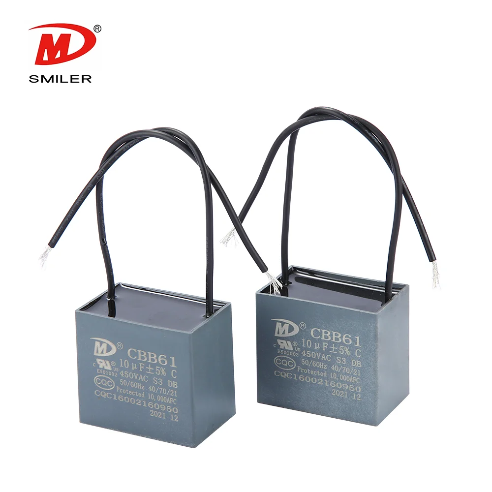
What Does a CBB61 Fan Capacitor Do? Exploring the Role of CBB61 Fan Capacitors
Understanding Why Capacitors Pass AC but Block DC in Circuits
What Drives AC Capacitor Cost? A Comparison with DC Capacitors
Snubbing Capacitors in Power Electronics: RC vs. RCD Snubber


 Add
Building 12,Huazhi Technology Innovation Center,28 Sanle East Road,Beijiao,Foshan,Guangdong,China
Add
Building 12,Huazhi Technology Innovation Center,28 Sanle East Road,Beijiao,Foshan,Guangdong,China
 Phone
+86 18007576965 / 0757-22391591
Phone
+86 18007576965 / 0757-22391591
 Email
ari@sml-cap.cn
Email
ari@sml-cap.cn


