

In today's power electronics, reaching good efficiency usually involves operating semiconductor devices near their boundaries. Yet, engineers often face a key challenge in high-frequency hard switching: harmful electrical surges. Adding a reliable rcd snubber circuit for IGBT modules is more than a simple addition. It serves as a basic need for system reliability and durability.
When an Insulated Gate Bipolar Transistor (IGBT) turns off large currents quickly, the built-in stray inductance in the DC busbar and connecting leads opposes this abrupt shift in current. Based on the simple inductor formula V = L * (di/dt), this fast current decrease creates large transient voltage spikes between the collector and emitter. If left unchecked, these spikes can quickly surpass the device's breakdown voltage limit. As a result, they cause major module damage, higher electromagnetic interference (EMI), and significant switching losses. These losses reduce the system's overall efficiency.

A snubber serves as a safeguard for your power semiconductors. When you add an rcd snubber circuit for IGBT modules, you change the switching path of the device in a basic way. The circuit offers another route for the inductive current at turn-off. It takes in the extra energy. It moves the power loss from the delicate semiconductor die to sturdy passive parts. This forward-thinking energy handling greatly cuts voltage peaks. It also reduces heat stress. Plus, it lengthens the working life of your high-power inverters and converters.
To get good at an RCD snubber design for IGBT modules, you need to grasp the linked actions of its three main parts first: the resistor, the capacitor, and the diode.
In a standard configuration, the snubber is connected directly across the collector (C) and emitter (E) terminals of the IGBT. The diode is placed in series with the capacitor, while the resistor is wired in parallel with the diode. This specific topology ensures that the circuit behaves differently during the turn-off and turn-on phases of the semiconductor, providing asymmetrical impedance when the system needs it most. If you are evaluating different protection strategies for your project, understanding the RC vs. RCD Snubber: Key Differences and Applications Explained is crucial for optimizing your specific application.
In the IGBT turn-off stage, the capacitor works as a short-term energy holder. As the voltage starts to rise sharply, the snubber capacitor takes up the energy from the unwanted layout inductance. It charges to control the speed of voltage increase (dv/dt) over the IGBT. Thus, it keeps the top voltage well inside the device's Safe Operating Area (SOA).
The diode and resistor act like guides for the held energy. When the IGBT switches off, the fast recovery diode turns forward-biased. It gives a low-resistance route. This lets the capacitor charge right away. On the other hand, when the IGBT switches on again, the diode turns reverse-biased. Now, the capacitor has to release its held energy via the resistor. The resistor turns this energy into heat without risk. It stops harmful LC oscillations. It also makes sure the capacitor empties completely and prepares for the following switching cycle.
A working RCD snubber design for IGBT uses calls for exact math work, not random tries. Here is the practical method to measure your parts correctly.
Before picking parts, you need to measure the stray inductance (Ls) in your DC loop. You can pull this out with modern 3D parasitic extraction software. Or, you can figure it out from experience using double-pulse testing. In that test, you check the ringing frequency. Getting Ls right forms the base of your whole design.
Measuring the capacitor calls for weighing good voltage control against too much energy holding.
Start by setting your top allowed peak voltage (Vpeak). Include a firm safety buffer. Usually, this means 15% to 20% under the full maximum voltage rating of your IGBT module. Factor in the toughest operating temperatures and load situations.
Apply the energy match rule to determine the needed capacitance (Cs). The energy in the stray inductance has to go into the capacitor. The usual formula is: Cs = (Ls * Io^2) / (Vpeak - VDC)^2, where Io stands for the top commutated current, and VDC means the steady DC bus voltage.
The resistor value (Rs) needs to be small enough to empty the capacitor before the next turn-off. But it should be large enough to cap the release current. You figure the power rating of the resistor with PR = 0.5 * Cs * VDC^2 * fsw, where fsw is the switching frequency. At the same time, the diode has to fit the voltage rating of the IGBT. It also needs a very quick reverse recovery time. This avoids shoot-through currents.

Basic formulas matter a lot. But hands-on figuring is what engineers count on. Let us go through a practical measuring case.
Imagine we are designing an inverter with the following parameters:
1. DC bus voltage (VDC): 600V
2. Maximum switching current (Io): 50A
3. Estimated stray inductance (Ls): 200nH
4. Switching frequency (fsw): 20kHz
5. Target maximum peak voltage (Vpeak): 800V
1. Snubber Capacitor: Cs = [200nH * (50A)^2] / (800V - 600V)^2 = 0.0005 / 40000 = 12.5nF. We will select a standard 15nF capacitor to provide a slight extra margin.
2. Resistor Power: The energy dissipated per cycle requires a robust resistor. PR = 0.5 * 15nF * (600V)^2 * 20kHz = 54W. A 60W or 75W wire-wound resistor is recommended.
3. Diode Rating: The diode needs to block at least the 800V peak, so a 1200V fast-recovery diode is the optimal choice for reliability.
Even with solid calculations, your circuit can break down if the base components cannot take the physical strain. The capacitor forms the core of the snubber. Its material features decide if your system lasts.
A useful snubber capacitor needs very low Equivalent Series Inductance (ESL). If the ESL gets too big, the capacitor adds its own ringing. This ruins the snubber's goal. Also, it must deal with high dv/dt (rate of voltage change). This helps it endure the high-frequency pulse currents. It avoids inner heat failure.
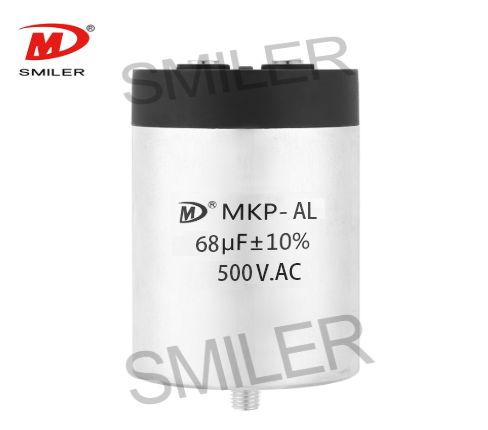
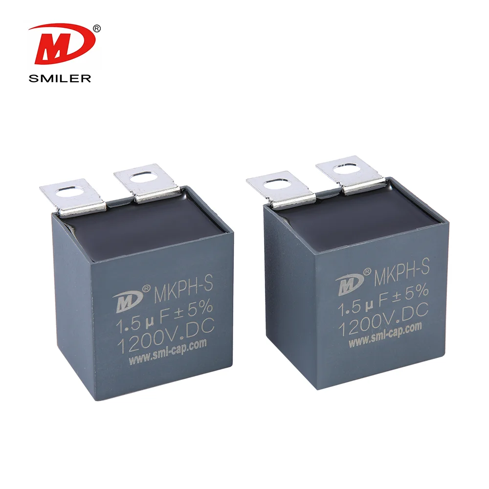
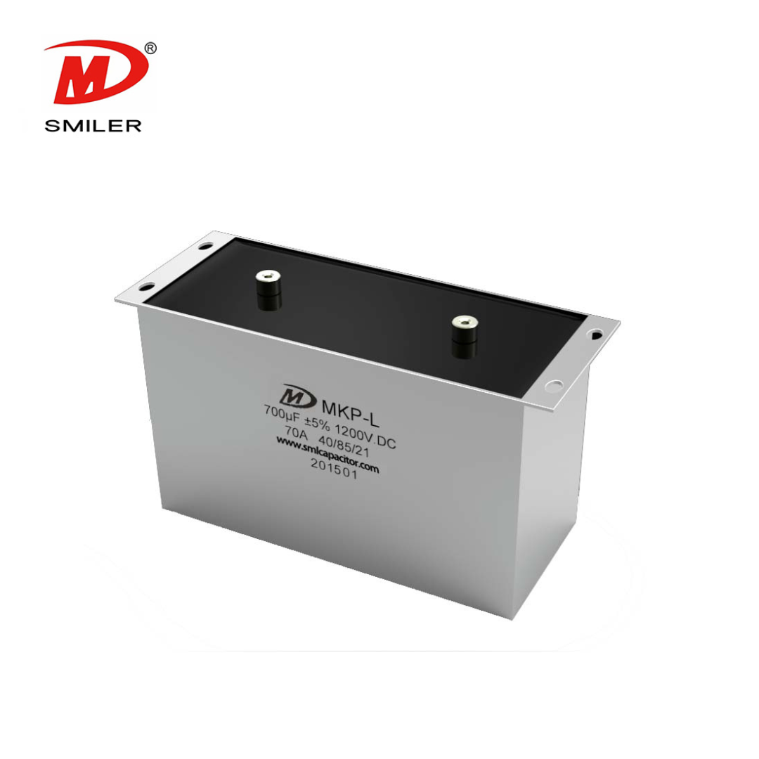
Unlike electrolytic or usual ceramic types, metallized film capacitors hold the clear top spot in power electronics. They give strong temperature stability, very low unwanted parameters, and a special "self-healing" feature. If a small dielectric failure happens from a tiny surge, the metallized film clears the area around the issue safely. This stops a major short circuit. It keeps the operation going without a stop.
Locating the right capacitance and shape for a particular layout can prove tough. This is where the SMILER capacitor stands out. With more than 15 years focused on film capacitor knowledge, SMILER capacitor offers custom fixes made just for tough IGBT uses. By running fully automated production lines, the company keeps a top product approval rate of over 99.93%. Companies in the Fortune Global 500, such as Midea and Home Depot, trust them. SMILER capacitor allows easy customization with a low MOQ. Their engineering group promises a quick reply. They deliver initial technical fixes in under 24 hours. This helps your R&D stay on time.
A: Making the snubber capacitor too big does hold back voltage spikes well. However, it makes the snubber resistor release too much energy in the turn-on stage. This causes large heat losses. It cuts your system's efficiency a lot. You also need big cooling setups for the resistor.
A: Ceramic capacitors do offer low ESL. But high-voltage ones tend to crack slightly under force and heat stress. They miss the self-healing traits of film capacitors. In strong-power IGBT setups, a broken ceramic capacitor often shorts out. That can wreck the whole semiconductor module at once.
A: Before fitting extra components, improve your physical setup. Switch to laminated busbars over loose cables. Make the space between the DC link capacitors and the IGBT terminals as brief as you can. Run the positive and negative traces near each other. This cancels magnetic fields.
A: Yes. The resistor and capacitor form an RC time constant (Time Constant = R * C). The capacitor needs sufficient time to empty fully through the resistor before the IGBT turns off once more. If your switching frequency rises too much, the capacitor stays charged. Then, the snubber loses all effect. It might even become risky.
A: Mount the snubber circuit as near as possible to the IGBT's collector and emitter power terminals. Keep it close in structure. If you put the snubber a few inches off, it adds fresh stray inductance to the snubber loop. This harms its power to take in high-frequency transient spikes badly.
2024 VIETNAM INTERNATIONAL ELECTRONICS & SMART APPLIANCES EXPO
Exploring How AC Capacitors and DC Capacitors Function Differently
Understanding Snubber Capacitor: RC vs. RCD Snubber Differences
Understanding DC Capacitance to Prevent Converter Oscillations
What Does a CBB61 Fan Capacitor Do? Exploring the Role of CBB61 Fan Capacitors


 Add
Building 12,Huazhi Technology Innovation Center,28 Sanle East Road,Beijiao,Foshan,Guangdong,China
Add
Building 12,Huazhi Technology Innovation Center,28 Sanle East Road,Beijiao,Foshan,Guangdong,China
 Phone
+86 18007576965 / 0757-22391591
Phone
+86 18007576965 / 0757-22391591
 Email
ari@sml-cap.cn
Email
ari@sml-cap.cn


