

DC filters in HVDC are not routine accessories that can be selected from voltage level alone. Their value depends on the harmonics produced by the converter, how those harmonics propagate through the DC circuit, and whether they can interfere with external infrastructure or create unacceptable stress inside the scheme. A sound decision therefore begins with the complete converter-route-network system.
Converters create non-sinusoidal voltages and currents as valves switch and commutate. The resulting spectrum depends on topology, firing or modulation, transformer stray capacitance, converter impedance, operating point, and the DC network. In LCC-HVDC, characteristic and non-characteristic components can propagate onto the line, while triplen harmonics may pass through converter-transformer stray capacitances. VSC and MMC stations normally produce much lower DC-side harmonic magnitudes, although an MMC can distribute small components across a wide frequency range.
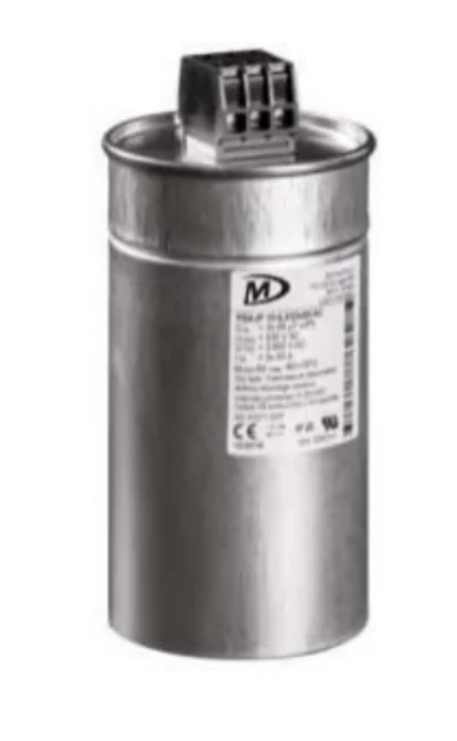
The best-known external concern is inductive coupling into nearby metallic communication or signalling circuits. Analogue telephone lines and railway signalling cables can be vulnerable, especially when they run parallel to an HVDC route. Digital and optical-fibre migration has reduced this exposure, but it has not eliminated it.
Internally, the DC circuit can amplify rather than simply transmit a harmonic. If pole-mode or ground-mode resonance falls near an emitted frequency, harmonic current and voltage may rise sharply. That can increase stress on capacitors, reactors, arresters, line insulation, and measuring equipment, while also disturbing control stability. These internal effects are why a project cannot judge filtering solely from telephone-interference risk.
LCC-HVDC generally deserves the most detailed DC-filter assessment because its emitted harmonic levels are typically higher and its converter-transformer capacitances affect propagation. A tuned or damped network may be required when calculated disturbing current, induced voltage, or internal harmonic stress exceeds the project limits.
VSC, MMC, and hybrid schemes often need less dedicated DC filtering. That is a tendency, not an exemption. The study still has to represent converter harmonic impedance, modulation, grounding, cable or line modes, controls, and operating configurations. Hybrid or multi-terminal arrangements may introduce new resonant paths and interactions even when each converter has low emissions in isolation.
Overhead lines can couple over long distances to parallel metallic infrastructure. Mixed overhead-cable routes add impedance transitions and resonance possibilities that should be included explicitly in the frequency-domain model. Shielded underground or submarine cables limit the geographic range of external fields, yet a cable installed very close to a telephone or signalling cable can still create a local interference risk.
Back-to-back stations have no long DC route, so third-party inductive coupling is usually much less important. Their decision is more likely to be driven by internal resonance, converter interaction, component stress, or control performance. Route separation, parallel length, earth resistivity, cable screening, grounding, and the vulnerability of adjacent circuits all influence the final risk.
A passive DC filter provides low impedance or damping around selected frequencies, diverting harmonic current away from the transmission path. This can reduce equivalent disturbing current and induced voltage in nearby conductors. The objective should be stated as a measurable system-performance requirement, rather than simply specifying that a filter must be installed.
The distinction between AC and DC filters also matters. AC filter capacitors support AC-side harmonic and reactive-power duties, whereas DC filters address components propagating through the DC circuit. One cannot automatically replace the function of the other.
Filters change network impedance, so a design that attenuates one frequency can create an undesirable peak elsewhere. Engineers should check the full frequency range, credible switching states, parallel poles, filter outages, line or cable combinations, and the active impedance of the converters. Component ratings must cover steady harmonic current, transient energy, overvoltage, thermal duty, and protection coordination.
More filter equipment means more capacitors, reactors, resistors, insulators, protection devices, and connections to inspect. It can also improve availability by preventing interference complaints, control instability, or overstress. The lifecycle optimum is therefore not the smallest installation or the highest attenuation; it is the design that meets limits with acceptable redundancy, losses, maintenance access, spares, and outage exposure.
Single-tuned, double-tuned, high-pass, and damped branches remain practical where dominant frequencies and system impedance are sufficiently predictable. Their advantages include continuous operation, mature components, and no separate power-electronic control. Their limitations include detuning, tolerance sensitivity, ageing, losses, and possible resonant interaction.
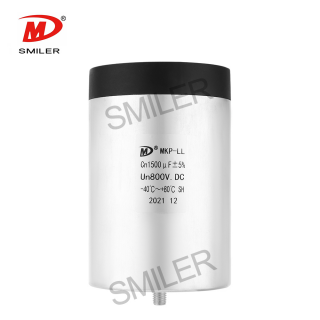
At SMILER capacitor, we present the Power Capacitor DC Link Capacitor MKP-LS as a component option for AC/DC filtering and high-frequency, high-current duty. Its published construction uses metallized polypropylene film, resin filling, and a plastic-shell or Mylar-tape housing. Listed features include low self-inductance, low ESR, heat dissipation, and current-impact capability. The published range is 500–1400 VDC and 1–200 µF, with IEC 61071 and GB/T 17702 referenced. These are component-level data; an HVDC bank still needs project-specific series-parallel design, insulation coordination, harmonic-current rating, cooling, protection, and reliability verification.
Active filtering can inject compensating components and adapt to changing operating conditions. Hybrid solutions combine a smaller passive network with active compensation. They may be attractive when the spectrum is broad or variable, but they add controls, sensors, auxiliary power, switching equipment, cybersecurity considerations, and failure modes. The business case should compare total losses, complexity, maintainability, and verified performance.
Smoothing reactors limit ripple and fault-current rise while influencing resonance. Converter design, control tuning, grounding, route changes, added screening, increased separation, and mitigation on the affected telecommunications circuit can all contribute. Component families such as DC-link capacitors should be evaluated within that coordinated system duty, not selected from capacitance and voltage alone. The best strategy is often coordinated rather than filter-only.
The study package should include converter harmonic sources and impedances, line and cable frequency-dependent models, grounding and earth resistivity, smoothing reactors, filter tolerances, adjacent metallic circuits, parallel exposure, operating configurations, and credible outages. Limits may be expressed through induced voltage or equivalent disturbing current, supplemented by internal voltage, current, thermal, and control-stability criteria.
Verification combines design-model checks, component type and routine tests, protection testing, commissioning measurements, and comparison with guaranteed criteria. Direct measurement of DC-conductor harmonics with sufficient phase and magnitude accuracy can be difficult. Where appropriate, induced-voltage measurement on a parallel test line can assess interference potential more directly. Results should be retained as a baseline for later condition and configuration reviews.
An ageing LCC scheme should not remove filters merely because analogue communications have declined. The reassessment must repeat the harmonic and resonance studies using the current converter controls, route, nearby infrastructure, operating modes, and equipment condition. Filters may still be justified by control stability, internal stress, or overvoltage suppression. Retain them when those duties remain material, redesign them when limits or resonances have changed, and remove them only when documented studies and measurements show that all external and internal requirements remain satisfied.
A: They attenuate DC-side harmonics to reduce induced interference and help control harmonic voltage, current, resonance, and equipment stress within the DC circuit.
A: No. The need depends on converter topology, route configuration, nearby metallic infrastructure, resonance, operating states, and the specified harmonic-performance limits.
A: Passive filters provide a low-impedance or damped path at relevant frequencies, so less harmonic current propagates along the DC route and couples into nearby conductors.
A: AC filters address AC-side harmonics and often reactive-power duties. DC filters address harmonics in the DC circuit and their external interference or internal stress effects.
A: Projects use modelling, component tests, protection checks, commissioning measurements, inspection, condition monitoring, and reassessment after changes to controls, topology, route, or adjacent infrastructure.
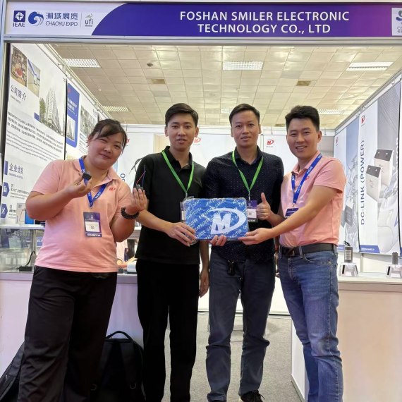
2024 VIETNAM INTERNATIONAL ELECTRONICS & SMART APPLIANCES EXPO
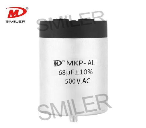
Exploring How AC Capacitors and DC Capacitors Function Differently
Understanding Snubber Capacitor: RC vs. RCD Snubber Differences
Understanding DC Capacitance to Prevent Converter Oscillations
What Does a CBB61 Fan Capacitor Do? Exploring the Role of CBB61 Fan Capacitors


 Add
Building 12,Huazhi Technology Innovation Center,28 Sanle East Road,Beijiao,Foshan,Guangdong,China
Add
Building 12,Huazhi Technology Innovation Center,28 Sanle East Road,Beijiao,Foshan,Guangdong,China
 Phone
+86 18007576965 / 0757-22391591
Phone
+86 18007576965 / 0757-22391591
 Email
ari@sml-cap.cn
Email
ari@sml-cap.cn



