

Choosing between motor-run capacitor families requires more than comparing two model codes. A CBB60 25uF 500VAC capacitor and a CBB61 capacitor can share the same metallized polypropylene dielectric and the same basic phase-shifting role, yet their normal load range, package geometry, connection options, and installation priorities are often different. The correct choice comes from the motor specification and operating environment, not from the series name alone.
In a permanent-split capacitor or capacitor-run motor, the capacitor creates a phase displacement between the main and auxiliary winding currents. The specified 25uF value helps establish the motor’s intended running torque, current balance, efficiency, and temperature rise. It is not a general “more torque” setting. Increasing capacitance beyond the motor design can raise auxiliary-winding current and heat, while a lower value can reduce torque and cause slow starting or humming. The motor maker’s specified microfarad value and tolerance must therefore control replacement selection.
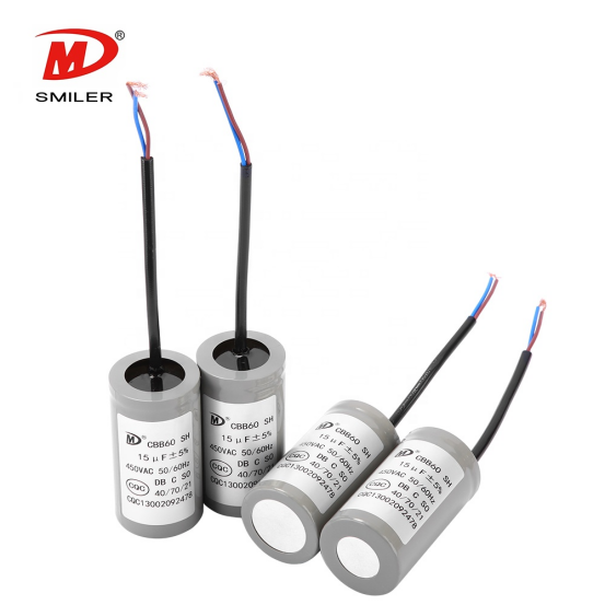
The 500VAC marking identifies an AC working-voltage class under the conditions defined for that component. It does not mean the motor must operate from a 500V supply, and it is not a substitute for a surge or impulse rating. A higher voltage rating provides dielectric margin only when frequency, temperature, life class, case size, and safety requirements also remain acceptable. The published CBB60 capacitor specifications include a 25uF dimension entry at 500VAC, confirming that this is a defined series combination rather than an assumed upgrade.
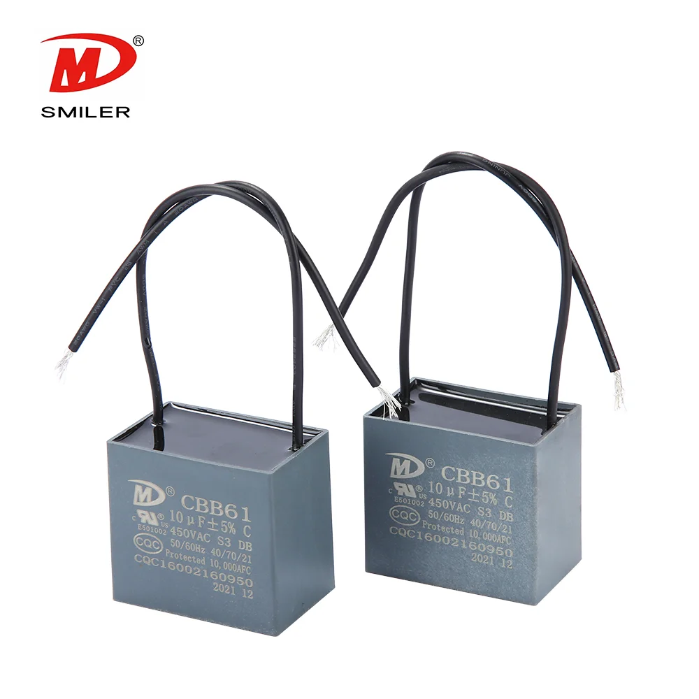
CBB61 capacitors also create the phase shift required by many single-phase AC motors. Their rectangular plastic cases fit conveniently inside ceiling fans, ventilators, air purifiers, and other appliances with shallow internal spaces. These loads often use lower capacitance than pumps or washing-machine motors, so the compact family is frequently optimized around smaller values. The CBB61 capacitor range nevertheless spans several AC voltage classes, showing that CBB61 is an application-oriented package family rather than a low-voltage-only technology.
A two-wire CBB61 unit usually contains one capacitance section for one motor circuit. Multi-wire versions may contain two or more sections or taps used by the fan’s speed-control arrangement. The wire count therefore cannot be ignored, even if one printed microfarad value appears familiar. Each lead must map to the correct section and switch connection. A cylindrical two-terminal CBB60 cannot reproduce a multi-section fan network unless the complete circuit is redesigned with equivalent values and connections. Photographs and wiring diagrams should be recorded before removal.
A 25uF motor-run requirement indicates a substantially different electrical load from a small fan using only a few microfarads. CBB60 products commonly cover wider or higher capacitance ranges for pumps, washing machines, shutters, range hoods, and other AC motors. CBB61 products are commonly selected for fans and ventilation appliances where compactness and small-value or multi-value configurations matter. These are typical application patterns, not hard electrical laws. A manufacturer can customize either family, so the approved datasheet must resolve any overlap.
CBB60 units are often cylindrical and may use wires, tabs, or a mounting stud. CBB61 units are commonly rectangular, resin-potted plastic boxes with wires or pins. Geometry affects available film volume, heat dissipation, vibration resistance, creepage distance, and installation security. A part that is electrically suitable but mechanically loose can suffer lead fatigue or abrasion. Conversely, forcing a large 25uF cylindrical unit into a fan enclosure can restrict airflow or contact moving parts. Functional compatibility includes the complete mechanical installation, not only the capacitance label.
Both families can use metallized polypropylene film, low-loss construction, resin encapsulation, and self-healing behavior. In normal motor-run service, both are non-polarized and remain connected while the motor operates. These shared features explain why their functions overlap. They also mean technicians should not describe every CBB60 as oil-filled or every CBB61 as a start-only capacitor. At SMILER capacitor, we define the application from the complete rating and construction rather than relying on a simplified label.
Film material alone does not establish capacitance tolerance, dissipation factor, permissible current, thermal endurance, life class, safety class, or terminal-to-case withstand capability. Winding design and metallization determine current distribution and self-healing behavior, while the enclosure controls heat transfer and environmental protection. Two capacitors made from polypropylene can therefore have different approved duty cycles. Buyers should compare the manufacturer’s specification sheet and required approvals for the exact ordering code instead of transferring ratings from another product in the same broad family.
The replacement must provide the motor-specified 25uF capacitance within an acceptable tolerance and an equal or higher appropriate AC voltage rating. Frequency, continuous-duty classification, operating temperature, expected life, dissipation factor, safety protection, and permissible current must also suit the circuit. Terminal arrangement and insulation distances must meet the original design. The practical CBB60 and CBB61 comparison reinforces why family, capacitance, voltage, and application must be evaluated together.
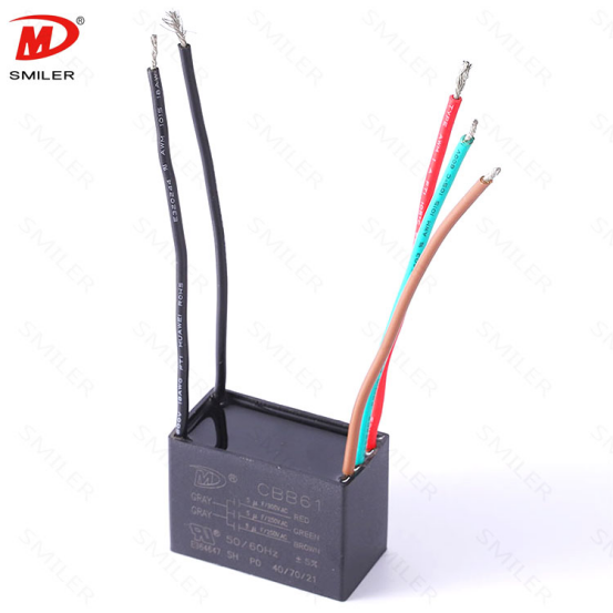
An equal 25uF/500VAC label does not confirm equivalent thermal behavior, life expectancy, safety class, case strength, or certification. A CBB61 offering with the same headline ratings might be custom-built, too large for the original space, or unsuitable for the motor’s continuous current. The public CBB61 size table is concentrated at lower capacitance values, so a 25uF version should never be presumed available without an exact datasheet. Replacement is acceptable only when the motor manufacturer or a qualified engineer confirms the full electrical and mechanical equivalence.
Choose CBB60 when the equipment calls for a single 25uF motor-run capacitor, needs the 500VAC class, and provides suitable cylindrical mounting space. Pumps, washing machines, shutter motors, and similar equipment often align with this format, but the original motor specification remains decisive. Our CBB60 range supports plastic or aluminum shell options and multiple voltage classes. Engineers should still confirm the exact dimension, terminal style, climatic category, life class, and safety approval before releasing a production or maintenance replacement.
Choose CBB61 when a compact rectangular package, fan-oriented mounting, insulated lead wires, or multiple capacitance sections are central requirements. It is often the natural fit for ceiling fans, ventilators, and air purifiers. Do not choose it merely because the equipment is physically small: the required capacitance, voltage, temperature, and wiring configuration must all match. The safest decision sequence is to identify the motor circuit, copy every original rating, verify available space, and then approve the exact manufacturer part number.
A: It is normally specified as a metallized polypropylene motor-run capacitor for continuous AC service. The word “start” may appear in broad marketing descriptions, but the exact motor circuit and datasheet determine whether a component is suitable for continuous operation.
A: Neither family is universally better. CBB61 commonly favors compact fan installations, while CBB60 commonly accommodates broader capacitance ranges and other motor loads. The better component is the exact approved part that matches the motor and enclosure.
A: Not on dielectric material alone. Replacement requires matching capacitance, suitable AC voltage, tolerance, continuous current, temperature, life and safety classes, terminal configuration, dimensions, and approvals. A custom CBB61 may qualify, but its exact datasheet must demonstrate equivalence.
A: With power isolated and stored charge safely discharged, verify capacitance and inspect the terminals and case. After qualified installation, measure motor current, startup behavior, running temperature, vibration, and noise under normal load, then confirm that all values remain within the equipment specification.
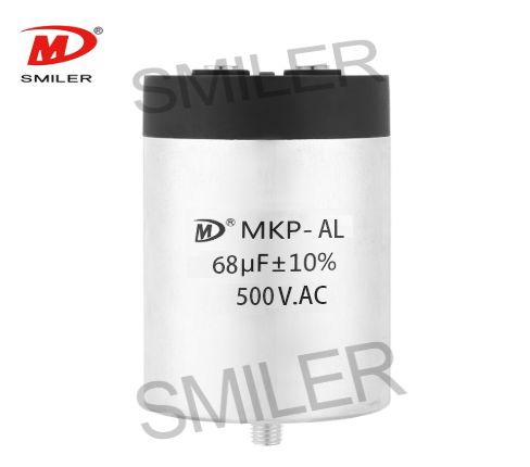
Exploring How AC Capacitors and DC Capacitors Function Differently
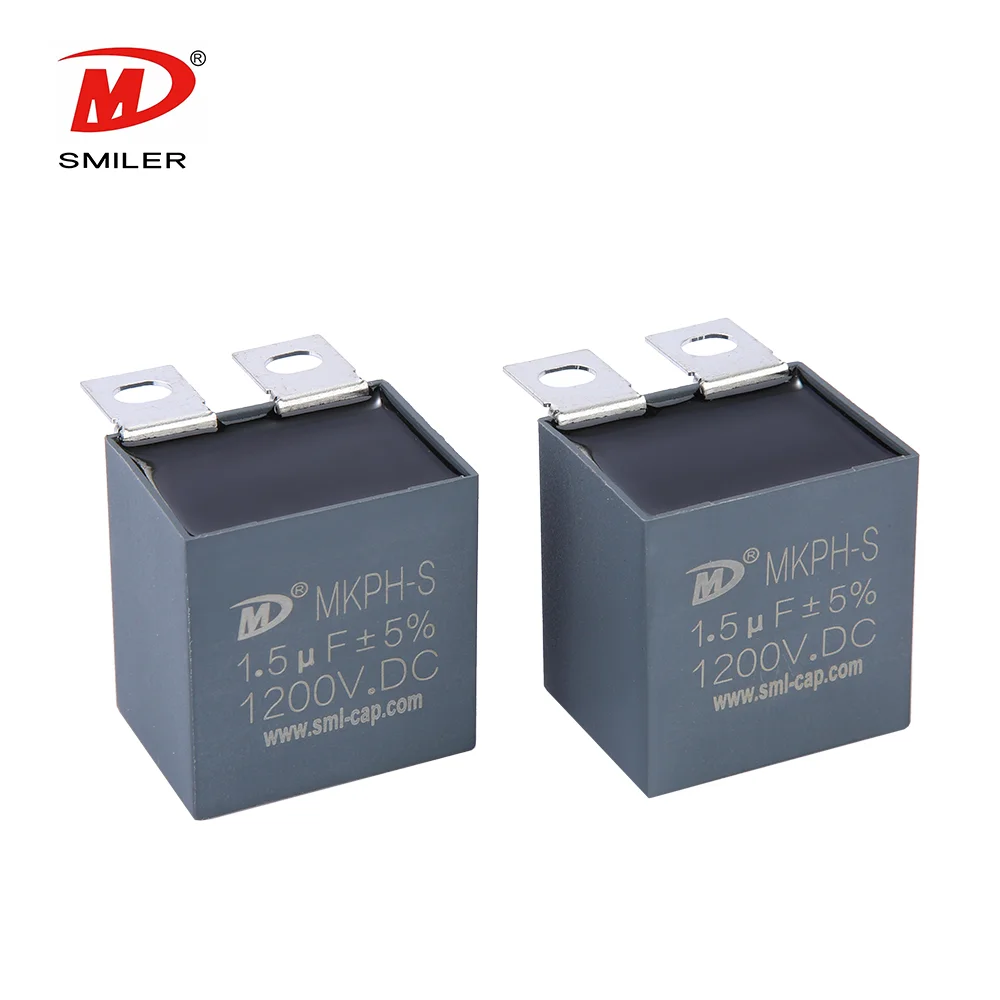
Understanding Snubber Capacitor: RC vs. RCD Snubber Differences
Understanding DC Capacitance to Prevent Converter Oscillations
What Does a CBB61 Fan Capacitor Do? Exploring the Role of CBB61 Fan Capacitors
Mastering AC to DC Rectifier with Capacitor Techniques


 Add
Building 12,Huazhi Technology Innovation Center,28 Sanle East Road,Beijiao,Foshan,Guangdong,China
Add
Building 12,Huazhi Technology Innovation Center,28 Sanle East Road,Beijiao,Foshan,Guangdong,China
 Phone
+86 18007576965 / 0757-22391591
Phone
+86 18007576965 / 0757-22391591
 Email
ari@sml-cap.cn
Email
ari@sml-cap.cn



