A ceiling fan sometimes hums. It may start slowly. Or it runs at just one speed. These signs could point to a weak CBB61 capacitor. Yet those signs do not prove the capacitor is defective. A safe test starts with the fan wiring diagram. It also needs the exact markings from the original part. This guide shows how to separate the capacitor. It covers how to discharge it. The steps include inspection and measurement. Then you interpret the outcome. This approach helps you avoid mixing a capacitor issue with a switch problem, motor fault, or wiring error.
A CBB61 serves as an AC motor capacitor. It is used in single-phase motors. In a ceiling fan circuit, its capacitance creates the phase relationship. This relationship is needed for motor torque and speed operation. Some fans use multiple capacitor sections. They also have extra leads for speed settings. So the wiring arrangement matters as much as the printed capacitance.
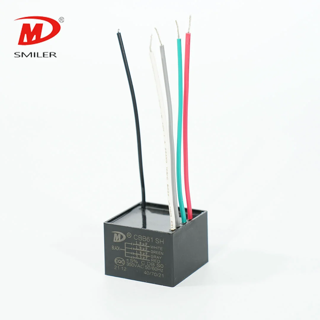
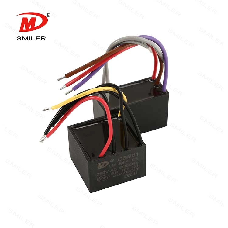
The SMILER capacitor CBB61 product uses metallized polypropylene film. It has a flame-retardant plastic shell and resin filling. The product information lists use with 50/60 Hz single-phase motors. These include fans and ventilators. Its published range covers 110-600 VAC and 0.40-12 μF. Tolerance options are ±5% (J) or ±10% (K). These are family ranges. They are not a specification for every fan. The replacement must match the equipment's required value and configuration.
The CBB61 construction uses metallized polypropylene film. It sits in a flame-retardant plastic shell with resin filling. Listed characteristics include low loss and low internal temperature rise. They also include high reliability, self-healing properties, and long lifetime for their intended motor-capacitor duty. The stated capacitance range and voltage range are selection references. They do not allow substitution of a random value.
The CBB61 product is specified for starting and running single-phase motors powered by 50/60 Hz AC. Listed applications include fans, ventilators, air purifiers, and other AC motors. Its rated voltage range is 110-600 VAC. Listed capacitance tolerances are ±5% (J) or ±10% (K). Capacitance options range from 0.40 μF through 12 μF. Dimensions vary with capacitance and rated voltage. These facts describe the family. They do not select a value for every ceiling fan.
Common clues include humming without starting. They also include weak starting torque, slow rotation, unstable speed, or failure on one or more speed settings. A capacitor can test fine while a wall control, pull-chain switch, winding, connector, or bearing is defective. Stop using a fan that smells burned. Do not use one that trips protection or becomes unusually hot. Arrange qualified service instead.
The AC motor capacitor categories provide broader product context when comparing package families after the test.
Turn off the fan circuit at the breaker. Do not rely only on the wall switch. Prevent accidental re-energizing. Then verify that the circuit is de-energized with a properly rated tester. If the ceiling canopy or wiring is inaccessible or unfamiliar, use a qualified electrician. Never measure resistance or capacitance on an energized circuit.
Before disconnecting anything, photograph the wiring. Label each lead clearly. Record every capacitance section, voltage rating, tolerance, lead count, and terminal marking on the old capacitor. A multi-value capacitor may have several wires. You cannot safely reconnect them by color alone. Use the fan manufacturer's diagram when available.
Even after power is isolated, a capacitor may retain charge. Follow the manufacturer's service procedure. Use a resistor-based discharge tool with appropriate voltage and energy ratings. Verify the voltage across the terminals with a meter. Do this before handling the leads. Do not discharge by shorting terminals with a tool. That can cause an arc. It can damage the component or injure the person performing the work.
If the capacitor is swollen, cracked, leaking, or burned, do not continue handling it as a routine test. Maintain isolation. Replace it only after its rating and wiring are confirmed.
Read the complete marking under good light. Note whether the part lists one capacitance value or several. Check the rated VAC, frequency, tolerance, and any common or speed leads. Compare the marking with the fan service information. A visually sound case does not establish electrical health. Visible damage is a strong reason to stop using the component.
Set a multimeter or LCR meter to capacitance mode. Confirm zero voltage first. Then disconnect at least one capacitor lead. This prevents other circuit components from distorting the reading. Connect the probes to the correct pair of terminals. For a multi-section capacitor, test each section according to its markings and diagram.
Compare each measured value with the marked capacitance and tolerance. For example, a value within a stated ±5% or ±10% band may match the label. Always use the actual capacitor marking and instrument accuracy. A reading near zero, an open circuit, or a value well outside tolerance indicates a problem. Poor probe contact or incorrect terminal selection can produce misleading results.
An ohmmeter can show a brief charging response. It does this as it applies a small test voltage. This is not a substitute for capacitance measurement. A stable open-like reading does not by itself confirm failure. Resistance behavior can vary with the meter and capacitor. Use capacitance mode when available. Have a technician test under suitable equipment if the result remains uncertain.
After testing, reconnect leads exactly as documented. Secure all covers before restoring power. If the measured capacitance is within tolerance but the fan still misbehaves, inspect the switch, wiring, motor, and mechanical load. Follow the service manual for this work. Avoid live testing unless performed by a qualified technician with suitable instruments and procedures.
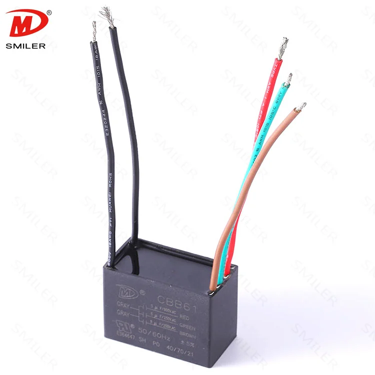
Use the original capacitance value. Or follow the fan manufacturer's specified replacement. For a multi-section unit, reproduce each value and connection. Do not increase capacitance to make the fan run faster. The replacement must also have a suitable AC voltage rating, frequency, motor-run duty, temperature capability, dimensions, and lead arrangement. A higher VAC marking alone does not make an otherwise mismatched part correct.
SMILER capacitor provides the CBB61 capacitor family for single-phase motor starting and running applications. The family listing helps identify construction and available ranges. It does not determine which value belongs in a particular fan. Review the fan requirements before purchasing.
Once the fan is safely reassembled, confirm that it starts without a push. It should respond to each speed setting. It must run without unusual hum, odor, or heat. If symptoms persist, turn it off. Seek diagnosis rather than repeatedly cycling it. CBB60 is another motor-capacitor family. Family names do not establish interchangeability. The application and original electrical requirements decide the correct part.
Our product support can review a clearly photographed nameplate and wiring arrangement when a buyer needs help identifying the relevant capacitor family. We still recommend using the fan manufacturer's specification for the final part value and connection diagram. See the CBB60 motor capacitor product page for a separate product family.
A: Isolate power. Discharge the capacitor using an appropriate method. Disconnect at least one lead. Measure capacitance across the correct terminals. Compare each value with its marking and tolerance.
A: It may hum. It might start slowly. It could run at reduced speed. Or it may fail on some settings. Those symptoms can also come from a switch, motor, wiring, or mechanical problem. So testing should isolate the cause.
A: Yes. Confirm that power is isolated. Follow a resistor-based discharge procedure appropriate to the component. Verify zero voltage with a suitable meter before touching terminals.
A: The acceptable band depends on the printed capacitance and tolerance, such as ±5% or ±10%. Use the exact marking and account for the meter's accuracy rather than assuming one value suits every fan.
A: Do not assume they are interchangeable. Confirm capacitance, voltage rating, duty, wiring, terminal arrangement, physical fit, and the fan manufacturer's requirements before selecting a replacement.
 Add
Building 12,Huazhi Technology Innovation Center,28 Sanle East Road,Beijiao,Foshan,Guangdong,China
 Phone
+86 18007576965 / 0757-22391591
 Email
ari@sml-cap.cn