

A ceiling fan may produce a humming sound. It can have trouble starting or run at reduced speeds. These signs often indicate a failing capacitor. First, you need to examine mechanical resistance. After that, match every original marking on the part. You must also follow the wiring arrangement. The case size needs to match too.
The motor receives energy in such cases. Yet it lacks the phase shift to generate starting torque. A worn capacitor often causes this issue. The blades may begin to move if you give them a gentle push. Avoid keeping the fan powered when it stays stalled. The motor heats up fast under these conditions.
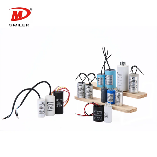
The fan might seem weaker than before on all speed positions. In this situation, the capacitor could have lost some of its capacitance. The motor still turns. However, it does not produce the expected torque. Other factors can create similar effects. These include supply-voltage issues, winding damage, or tight bearings. Therefore, slow operation by itself does not confirm the problem.
Many fans rely on a multi-value capacitor. They may use several capacitor sections to achieve different speeds. When one section fails, a single speed can disappear. The other speeds might stay available. Intermittent connections in the switch or wiring can create the same effect.
Dust buildup, dry bearings, a bent bracket, loose connectors, a damaged speed switch, low voltage, or a failing winding can lead to noise or lower speed. Humming may also result from loose hardware.
Turn off the breaker first. Then confirm that the fan cannot start on its own. Spin the blades by hand after that. They should turn smoothly without any scraping or stiffness. Fix any mechanical drag before you proceed. When the movement feels free, inspect the capacitor. Look for swelling, cracking, leakage, burned terminals, or loose wires.
The microfarad value appears as μF, uF, or sometimes MFD. This value shows the capacitance. It controls the current and phase relationship in the auxiliary motor winding. The original value serves as the main matching specification. A label that reads 2.5 μF means the replacement needs the same nominal capacitance. You must respect the stated tolerance.
SMILER capacitor lists its CBB61 fan capacitor for starting and running single-phase AC motors, including fans, ventilators, and air purifiers. The published family covers 0.40-12 μF. However, that range does not serve as a universal recommendation for every fan.
The CBB61 construction uses metallized polypropylene film. It sits in a flame-retardant plastic shell. Listed characteristics include low loss and low internal temperature rise. The part offers high reliability, self-healing property, and long lifetime. These features suit its intended motor-capacitor duty.
VAC represents the capacitor's AC voltage rating. It does not indicate the fan speed. The CBB61 source range covers 110-600 VAC at 50/60 Hz. A higher safe voltage rating can make the capacitor larger in size. Yet it does not raise the capacitance value. Tolerance indicates how much the actual capacitance may vary from the marked value. Common source markings include ±5% (J) and ±10% (K).
A marking such as 1.5+2.5 μF shows separate capacitance sections. These sections share a common connection. Wire colors and the printed circuit diagram show which lead belongs to each value. Record every connection before you remove the old part. Never assume that the same wire color serves the same function on a different capacitor.
The motor and speed circuit were designed around specific capacitance values. Matching the original μF rating keeps the intended phase shift and torque. If the label says 2.5 μF ±5%, select 2.5 μF. Choose an equal or tighter appropriate tolerance. Do not pick the nearest value that simply fits the space.
A replacement with the same capacitance works in many cases. It can have an equal or higher VAC rating. This choice remains acceptable if the construction suits continuous AC motor service. The part must also fit safely in the space. Never use a lower voltage rating. Check the manufacturer's instructions when the circuit design or capacitor type seems uncertain.
SMILER capacitor also offers a CBB60 running capacitor for single-phase 50/60 Hz motor starting and running. Product-family similarity does not prove interchangeability. Capacitance, voltage, duty, terminals, and dimensions still need to match the fan requirements.
Match the number of leads or terminals. Pay attention to each section value and the common lead. The original circuit layout needs to stay the same. Compare case length, width, height, mounting method, and lead reach. SMILER capacitor's CBB61 data shows that dimensions change with both capacitance and rated voltage. Electrical compatibility does not guarantee a physical fit as a result.
Too little capacitance reduces both starting torque and running torque. The fan may hum in this case. It might need a push to start. Acceleration can occur slowly. The unit may fail to reach normal speed. The motor draws current for a longer time while it struggles to start. This process increases heat buildup.
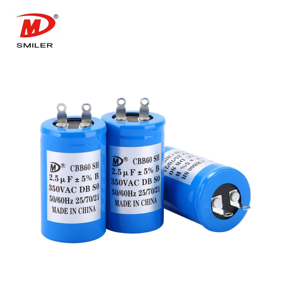
Excess capacitance does not safely increase fan speed. It alters auxiliary-winding current and phase angle instead. This change may raise noise levels. It can also produce more heat, vibration, or winding stress. The fan might appear faster at times. However, operation outside the designed value can shorten the life of the motor or switch.
The replacement may have incorrect wiring. Poor connections can exist as well. The new part might turn out defective. The fan could suffer from bearing resistance. A faulty speed switch often creates problems. Damaged windings, low voltage, or loose mechanical parts produce similar effects. A correct rating only removes one possible cause from consideration.
Switch off the breaker. Verify de-energization with a suitable tester after that. Follow the manufacturer's discharge instructions too. Take photographs of the wiring. Label each connection clearly. Stop the process if conductors appear burned. The same applies if they look brittle, remain unidentified, or could contact moving parts.
Reassemble the housing before you restore power. Begin at the lowest speed during testing. Check every setting in order. The fan should start without any outside help. It needs to change speeds in a predictable way. Operation should occur without excessive hum, vibration, odor, or heat. Allow it to run long enough to show any unstable connection. Then switch it off. Confirm that no part has moved out of place.
For appliance and motor applications, the CBB65 capacitor range includes fans among its listed uses. Our product range illustrates an important point. The label, circuit, and duty must be checked together. Selecting by appearance alone leads to mistakes.
Call a qualified electrician under certain conditions. These include when the breaker trips repeatedly. Discolored wiring calls for professional help. The same applies if the motor gives off a burned smell. Unstable voltage requires attention too. An unreadable capacitor label creates uncertainty. The fan may continue to hum after a verified replacement. Professional testing makes sense when the fan uses an electronic controller. Remote receivers or unfamiliar multi-wire circuits also suggest the need for expert assistance.
A: Use the capacitance value printed on the original capacitor. You can also refer to the value specified by the fan manufacturer. Match every μF section carefully. Then select an equal or higher suitable VAC rating. Keep the same wiring arrangement as well.
A: It may change the speed somewhat. However, it also affects motor current and phase angle. A higher-uF capacitor can lead to extra heat. It may increase noise or winding stress. Therefore, you should not use it as a way to upgrade speed.
A: This option often works well. The μF value must stay the same. The capacitor type, frequency suitability, wiring, and physical fit all need to match. Never replace the original part with a lower VAC rating.
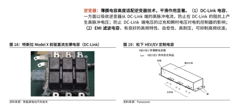
2025 EV Main Drive Inverter Technologies: How Capacitors Enhance Inverter Performance and Reliability
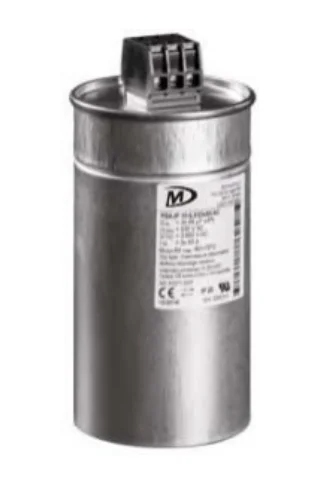
AC vs. DC Capacitors: Unveiling the Critical Distinctions

Wind Turbine Inverters 2025: How Capacitors Ensure Longevity
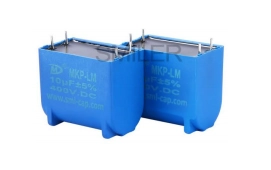
Unveiling the Function of Capacitor with DC Source in Electronics
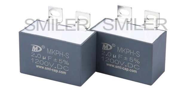
Comparing Buck, Boost, and Buck-Boost Converters: Capacitor Roles


 Add
Building 12,Huazhi Technology Innovation Center,28 Sanle East Road,Beijiao,Foshan,Guangdong,China
Add
Building 12,Huazhi Technology Innovation Center,28 Sanle East Road,Beijiao,Foshan,Guangdong,China
 Phone
+86 18007576965 / 0757-22391591
Phone
+86 18007576965 / 0757-22391591
 Email
ari@sml-cap.cn
Email
ari@sml-cap.cn



