DC-Link Capacitor sizing in an EV charging station does not come from a simple power-to-capacitance table. A DC fast charger often receives its rating at the cabinet level. Yet the real capacitor stress depends on many separate factors. These factors include module power. They also include bus voltage, ripple waveform, current, frequency, temperature, cooling, and lifetime. A practical process includes three steps. First comes calculation. Next is the stress check. Last comes capacitor-bank validation.
Start with one fast charger power module. Do not use only total station power. A cabinet may use several 20 kW, 30 kW, or 40 kW modules. These modules may have independent or shared DC links. Define module power first. Then set the DC-link voltage range. Include transient voltage. List allowable ripple. The current waveform matters. Hold-up requirement also needs clear definition. Only after these steps can you estimate capacitance.
The DC-Link Capacitor value comes from those inputs. It is not an initial assumption.
PFC and isolated DC/DC stages create different ripple parts. Rectifier, PFC, LLC, bridge, and SiC switching choices affect RMS ripple current. They also change the frequency spectrum and hotspot temperature. Avoid one sizing formula for every architecture.
Capacitance does not protect reliability by itself. Set ambient temperature early. Define hotspot limit, airflow, mounting, operating hours, and service-life target at the same time. Ripple current creates heat. Temperature then affects usable capacitor life.
The basic relationship is C = Delta Q / Delta V. In a known-waveform case, engineers may estimate C approx I / (f × ΔV). Here, I is the evaluated current component. f is the dominant frequency. Delta V is the allowed ripple. This is only a preliminary check.
Mains-related ripple appears at one frequency. PFC ripple current appears at another. DC/DC switching ripple appears at yet another. Evaluate RMS current instead of adding peak currents. Then check capacitance. Next, review voltage ripple, ESR loss, ESL behavior, and heat rise. Perform these checks across light, full, and peak load.
For an illustrative 30 kW module on an 800 V DC bus, average current is about 37.5 A. If a simplified 20 A ripple component is checked at 20 kHz, the result is about 125 uF at 1 percent ripple. It is 62.5 uF at 2 percent. It is 25 uF at 5 percent. These are not final part selections.
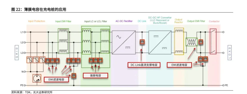
A capacitor can meet calculated capacitance and still fail. This happens if the RMS ripple-current rating is too low. The HEV/EV onboard charger application separates EMI Capacitors, DC Link Capacitors, and DC Capacitor (Resonant) positions. Each part must be selected for its own electrical stress. Capacitance value alone is not enough.
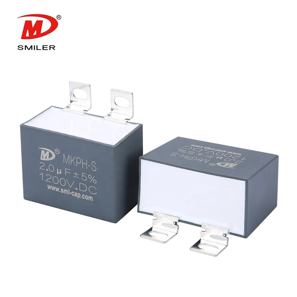
ESR converts ripple current into heat. Use P approx Irms^2 x ESR. Then check ESR at the actual ripple frequency and temperature. SMILER capacitor DC-Link Capacitor products use metallized polypropylene film. They are used in DC-Link circuits.
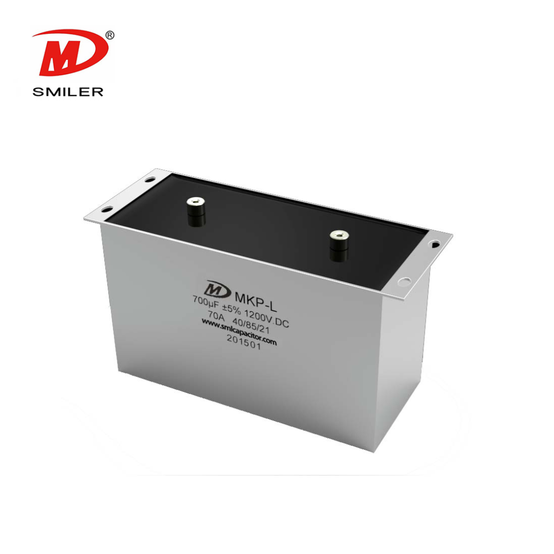
Fast SiC switching makes parasitic inductance more important. Capacitor ESL affects overshoot. Terminals, busbar symmetry, and current-loop length also play a role. This DC-link family lists low ESR. It offers high ripple current handling capability. It provides low self-inductance, a self-healing property, and long lifetime. Applications include EV or HEV transportation and renewable-energy inverters.
Vehicle battery voltage is not the same as the internal charger DC-link voltage. The bus depends on PFC, isolation, control strategy, and output range. An 800V fast charger capacitor decision should include steady-state voltage. It must also consider surge margin, overshoot, insulation spacing, and derating.
The HEV/EV onboard charger scenario lists DC-link capacitors for DC filtering and smoothing. Capacitance ranges from 1 uF to 170 uF. Voltage ranges from 450 VDC to 1200 VDC. That OBC DC-link position is marked Automotive Grade (AEC-Q200). A fast charger can use a different range. Real bus stress still controls selection.
A public charger may serve Tesla, Porsche, Hyundai, Kia, Audi, and other EV platforms. These platforms have different charging profiles. Size the capacitor for the charger operating envelope. Include repeated peak-load events. Consider module sharing as well. Do not size it for one vehicle brand.
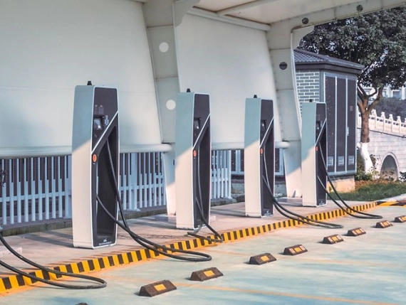
In an EV fast charger application, higher station power often comes from more modules. It does not come from one larger DC bus. Evaluate per-module capacitance. Check shared-bus interaction. Review redundancy, thermal distribution, and current sharing.
Film and electrolytic capacitors solve different constraints. Electrolytics can offer high capacitance density. They may also have lower initial cost. Yet ripple current, heat, and electrolyte aging may limit service life. DC-link film capacitor designs often fit high-ripple and long-life systems.
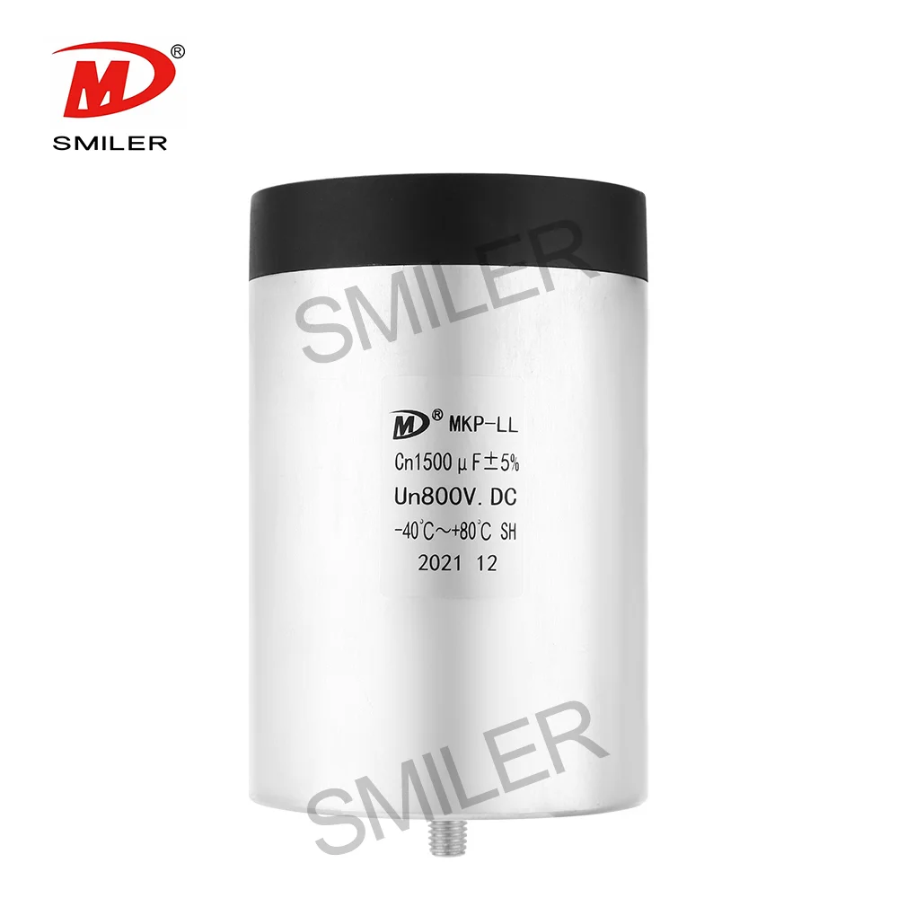
The Power Capacitor DC Link Capacitor MKP-LL is a dry-type aluminum-case DC link capacitor used for DC filtering and smoothing. It is used in DC-Link circuits. Voltage ranges from 600 VDC to 4000 VDC. Rated capacitance ranges from 24 uF to 5600 uF. Its product facts include low ESR, high ripple current handling capability, low self-inductance, self-healing property, and long lifetime.
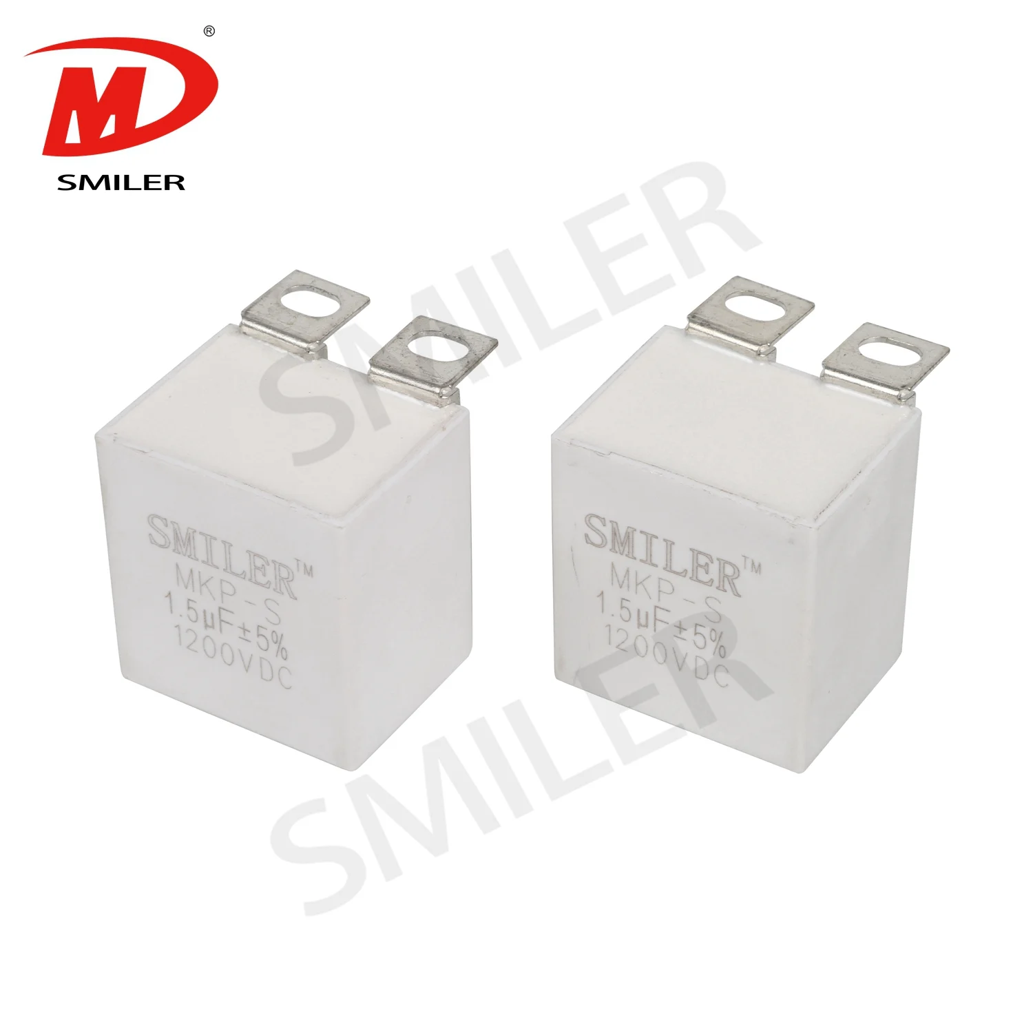
For parallel DC-Link Capacitors, verify total capacitance first. Then confirm ripple-current capability. After that, check current sharing. Tolerance, ESR spread, busbar geometry, terminal inductance, and local cooling can make one part hotter than another.
Move from calculation to simulation. Then go to prototype testing. Measure DC bus ripple voltage. Check RMS ripple current. Record hotspot temperature and switching overshoot. Test voltage extremes. Test load range, overload, high temperature, and fault response.
SMILER capacitor has over 15 years of film capacitor expertise. Engineers should provide the rated and surge voltage. They need to share the capacitance target. RMS ripple current by frequency is important. Switching frequency matters too. Ambient and hotspot temperatures must be listed. Lifetime target is required. Size limit, terminal preference, insulation requirement, busbar layout, and cooling method complete the list. Our selection work can compare these requirements against suitable DC-Link Capacitor specifications.
Customization makes sense when a standard part cannot meet electrical and mechanical requirements together. Key variables include voltage, capacitance, ripple current, dimensions, terminals, mounting, and thermal path. Our customization support, low MOQ availability, and automated production lines are designed for efficiency, precision, consistency, and quality control.
A: Start with module power, DC-link voltage, allowable ripple, and waveform frequency. Use C = Delta Q / Delta V. Then validate ripple current, ESR, ESL, temperature, and lifetime.
A: It depends on the internal DC bus. It is not based only on vehicle battery voltage. Include steady-state voltage, surge voltage, switching overshoot, insulation, margin, and derating.
A: It should handle RMS ripple current from the actual PFC and DC/DC stages. This must cover load, voltage, frequency, and temperature conditions. Capacitance alone is not enough.
A: Not always. Film capacitors can suit high-ripple, low-ESR, long-life applications. Electrolytic capacitors may fit cost-sensitive or high-capacitance-density designs. The stress profile decides.
A: ESR drives ripple-current heating and hotspot temperature. ESL affects overshoot, ringing, and current-loop behavior. SiC layouts need low-inductance capacitors, busbars, and routing.
 Add
Building 12,Huazhi Technology Innovation Center,28 Sanle East Road,Beijiao,Foshan,Guangdong,China
Add
Building 12,Huazhi Technology Innovation Center,28 Sanle East Road,Beijiao,Foshan,Guangdong,China
 Phone
+86 18007576965 / 0757-22391591
Phone
+86 18007576965 / 0757-22391591
 Email
ari@sml-cap.cn
Email
ari@sml-cap.cn